


3 - 39
3. SIGNALS AND WIRING
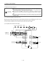
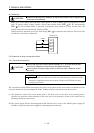
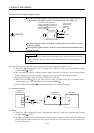
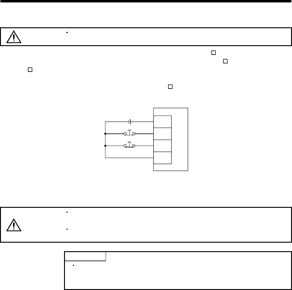
(3) Forced stop
CAUTION
Install an forced stop circuit externally to ensure that operation can be stopped and
power shut off immediately.
Make up a circuit which shuts off main circuit power as soon as EMG_ -SG are opened at a forced
stop. To ensure safety, always install a forced stop switch across EMG_
-SG. By disconnecting
EMG_
-SG, the dynamic brake is operated to bring the servo motor to a stop. At this time, the
display shows the servo forced stop warning (A.E6).
During ordinary operation, do not use forced stop (EMG_
) to alternate stop and run. The service life
of each drive unit may be shortened.
VIN
EMG_A
EMG_B
SG
Interface unit
24VDC
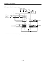
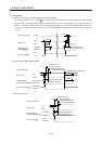
3.5 Connection of drive unit and servo motor
3.5.1 Connection instructions
CAUTION
Connect the wires to the correct phase terminals (U, V, W) of the drive unit and
servo motor. Otherwise, the servo motor will operate improperly.
Do not connect AC power supply directly to the servo motor. Otherwise, a fault
may occur.
POINT
Do not apply the test lead bars or like of a tester directly to the pins of the
connectors supplied with the servo motor. Doing so will deform the pins,
causing poor contact.
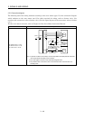
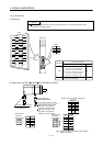
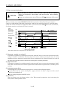
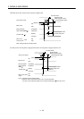
The connection method differs according to the series and capacity of the servo motor and whether or not
the servo motor has the electromagnetic brake. Perform wiring in accordance with this section.
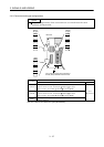
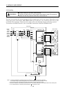
(1) The protective earth of the servo motor joins to the base unit via the drive unit mounting screw.
Connect the protective earth terminal of the base unit to the protective earth of the control box to
discharge electricity to the earth.
(2) The power supply for the electromagnetic brake should not be used as the 24VDC power supply for
interface. Always use the power supply for electromagnetic brake only.