


3 - 4
3. SIGNALS AND WIRING
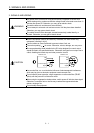
Note 1. To prevent an electric shock, always connect the protective earth (PE) terminal (terminal marked ) of the base unit to the
protective earth (PE) of the control box.
2. Connect the diode in the correct direction. If it is connected reversely, the servo amplifier will be faulty and will not output signals,
disabling the forced stop and other protective circuits.
3. The forced stop switch (normally closed contact) must be installed.
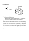
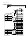
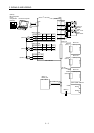
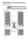
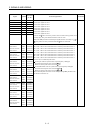
4. CN1A
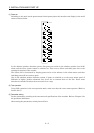
CN1B, CN4A CN4B have the same shape. Wrong connection of the connectors will lead to a fault.
5. CN2 and CN3 have the same shape. Wrong connection of the connectors can cause a fault.
6. When starting operation, always connect the forced stop (EMG_A) and forward/reverse rotation stroke end (LSN
/LSP ) with
SG. (Normally closed contacts)
7. Trouble (ALM_
) is connected with COM in normal alarm-free condition. When this signal is switched off (at occurrence of an
alarm), the output of the programmable controller should be stopped by the sequence program.
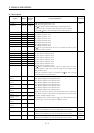
8. Always connect P5-OP_VIN when using the 5V output (P5). Keep them open when supplying external power.
9. Use MRZJW3-SETUP151E.
10. Refer to Section 3.3 for the MR-J2M-D01 extension IO unit.
11. The MR-J2M-BT battery unit is required to configure an absolute position detection system. Refer to Chapter 14 for details.
12. When connecting the personal computer together with monitor outputs 1, 2, use the maintenance junction card (MR-J2CN3TM).
(Refer to Section 12.1.2)
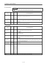
13.
in Symbol indicates a slot number.