


5 - 8
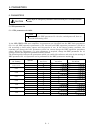
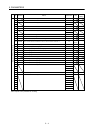
5. PARAMETERS
Class No. Symbol Name and function
Initial
value
Unit
Setting
range
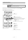
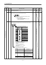
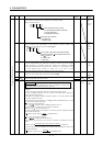
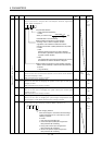
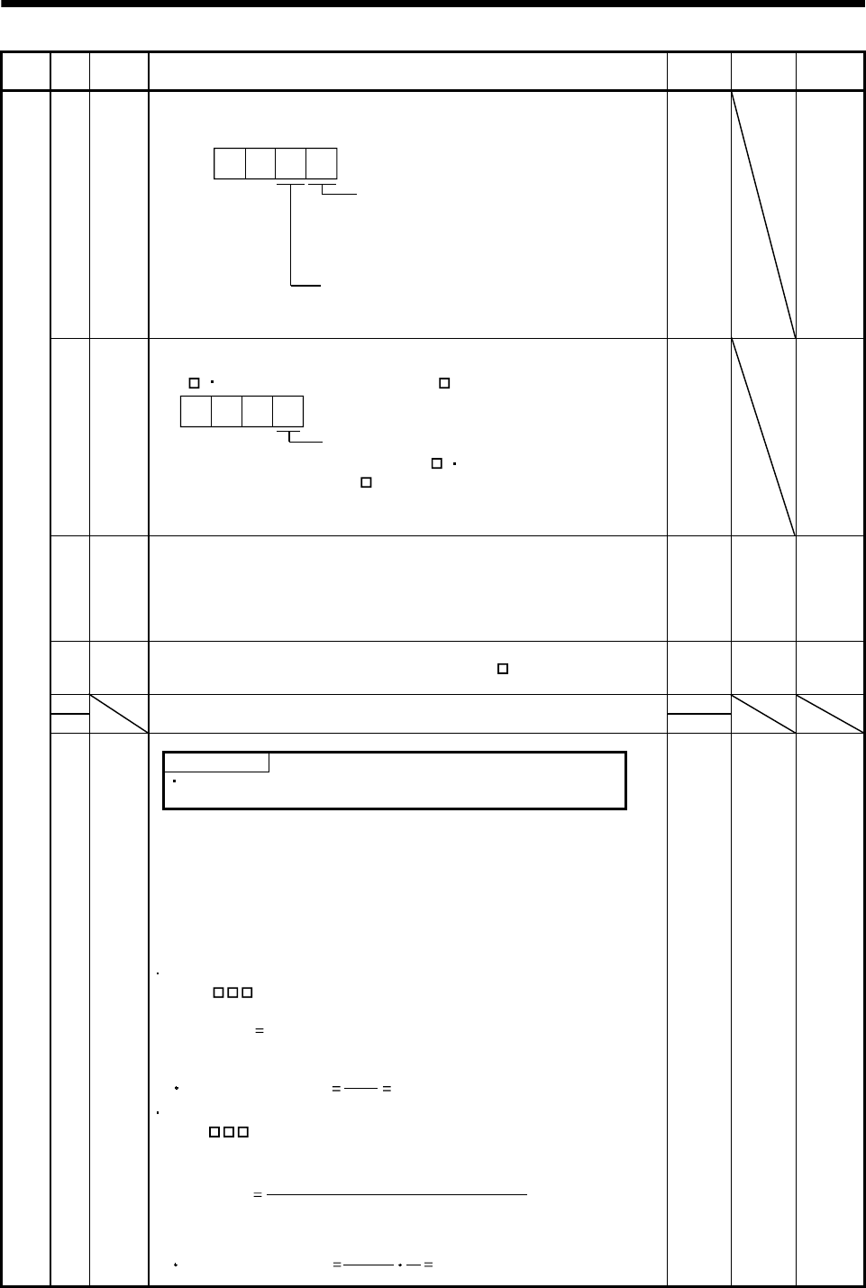
21 *OP3 Function selection 3 (Command pulse selection)
Used to select the input form of the pulse train input signal.
(Refer to Section 3.2.3.)
Command pulse train input form
0: Forward/reverse rotation pulse train
1: Signed pulse train
2: A/B phase pulse train
Pulse train logic selection
0: Positive logic
1: Negative logic
0 0
0000
Refer to
Name
and
function
column.
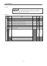
22 *OP4 Function selection 4
Used to select stop processing at the forward rotation stroke end
(LSP
)
reveres rotation stroke end (LSN
)
off.
How to make a stop when the forward rotation
stroke end (LSP ) reveres rotation stroke end
(LSN ) is valid.
0: Sudden stop
1: Slow stop
0
0
0
0000
Refer to
Name
and
function
column.
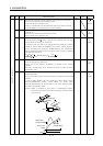
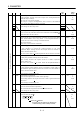
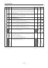
23 FFC Feed forward gain
Set the feed forward gain. When the setting is 100%, the droop pulses
during operation at constant speed are nearly zero. However, sudden
acceleration/deceleration will increase the overshoot. As a guideline, when
the feed forward gain setting is 100%, set 1s or more as the
acceleration/deceleration time constant up to the rated speed.
0%0
to
100
24 ZSP Zero speed
Used to set the output range of the zero speed (ZSP
).
50 r/min 0
to
10000
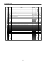
25 0
26
For manufacturer setting
Do not change this value any means.
100
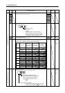
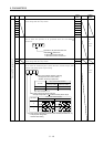
Encoder output pulses
POINT
The MR-J2M-D01 extension IO unit is required to output the
encoder pulses (A phase, B phase, Z phase).
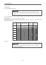
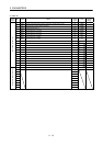
Expansion DRU parameters 1
27 *ENR
Used to set the encoder pulses (A-phase, B-phase) output by the servo
amplifier.
Set the value 4 times greater than the A-phase or B-phase pulses.
You can use DRU parameter No. 54 to choose the output pulse setting or
output division ratio setting.
The number of A/B-phase pulses actually output is 1/4 times greater than
the preset number of pulses.
The maximum output frequency is 1.3Mpps (after multiplication by 4). Use
this parameter within this range.
For output pulse designation
Set " 0
" (initial value) in DRU parameter No. 54.
Set the number of pulses per servo motor revolution.
Output pulse
set value [pulses/rev]
At the setting of 5600, for example, the actually output A/B-phase pulses
are as indicated below:
4
5600
A B-phase output pulses 1400[pulse/rev]
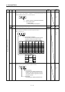
For output division ratio setting
Set " 1
" in DRU parameter No. 54.
The number of pulses per servo motor revolution is divided by the set
value.
Output pulse
[pulses/rev]
Resolution per servo motor revolution
Set value
At the setting of 8, for example, the actually output A/B-phase pulses are
as indicated below:
A B-phase output pulses 4096[pulse/rev]
8
131072
4
1
4000 pulse/
rev
1
to
65535