


13 - 11
13. COMMUNICATION FUNCTIONS
13.11 Command and data No. list
POINT
If the command/data No. is the same, its data may be different from the
interface and drive units and other servo amplifiers.
The commands/data No. of the respective interface unit and drive units are those marked in the Unit
field.
13.11.1 Read commands
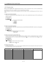
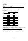
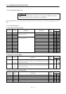
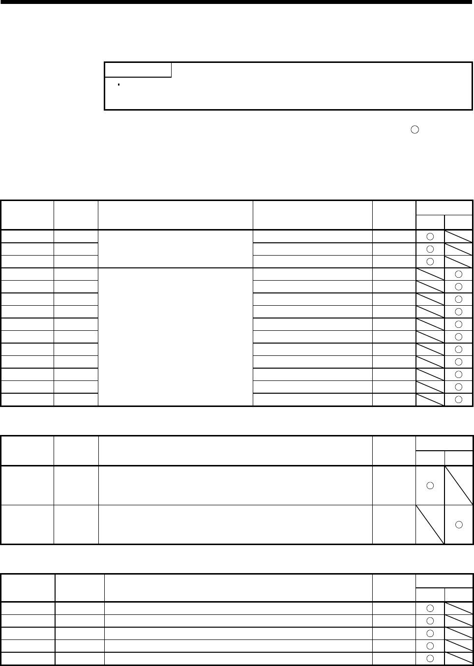
(1) Status display (Command [0][1])
Unit
Command Data No. Description Display item
Frame
length
IFU DRU
[0][1] [8][0] regenerative load ratio 12
[0][1] [8][1] Bus voltage 12
[0][1] [8][2]
Status display data value and
processing information
Peak Bus voltage 12
[0][1] [8][0] cumulative feedback pulses 12
[0][1] [8][1] Servo motor speed 12
[0][1] [8][2] droop pulses 12
[0][1] [8][3] cumulative command pulses 12
[0][1] [8][4] command pulse frequency 12
[0][1] [8][5] effective load ratio 12
[0][1] [8][6] peak load ratio 12
[0][1] [8][7] Instantaneous torque 12
[0][1] [8][8] within one-revolution position 12
[0][1] [8][9] ABS counter 12
[0][1] [8][A]
Status display data value and
processing information
load inertia moment ratio 12
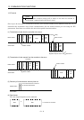
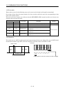
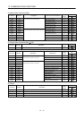
(2) Parameter (Command [0][5])
Unit
Command Data No. Description
Frame
length
IFU DRU
[0][5] [0][0]
to
[1][D]
Current value of each parameter
The decimal equivalent of the data No. value (hexadecimal) corresponds
to the parameter number.
8
[0][5] [0][0]
to
[5][4]
Current value of each parameter
The decimal equivalent of the data No. value (hexadecimal) corresponds
to the parameter number.
8
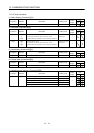
(3) External I/O signals (Command [1][2])
Unit
Command Data No. Description
Frame
length
IFU DRU
[1][2] [4][0] External input pin statuses 8
[1][2] [4][1] External input pin statuses 8
[1][2] [4][3] External input pin statuses 8
[1][2] [C][0] External output pin statuses 8
[1][2] [C][1] External output pin statuses 8