


3 - 37
3. SIGNALS AND WIRING
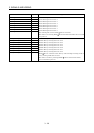
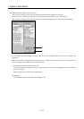
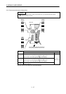
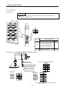
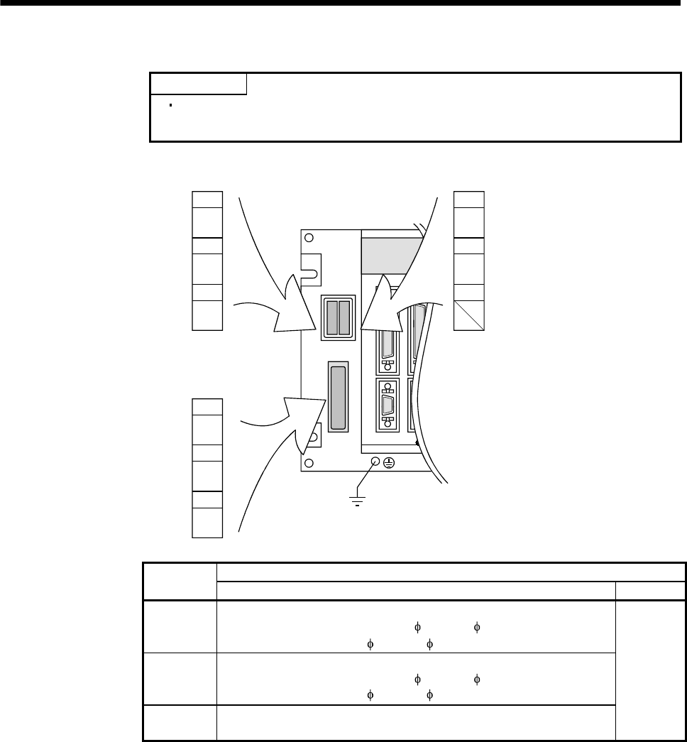
3.4.2 Connectors and signal configurations
POINT
The pin configurations of the connectors are as viewed from the cable
connector wiring section.
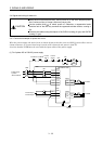
1
3
2
2
3
1
N
P
C
L
3
L
2
L
1
CNP3
1
2
3
L
11
L
21
CNP1A
Base unit
(X type) (Y type)
The connector frames are connected to
the PE (earth) terminal of the base unit.
CNP1B
Cable side connector
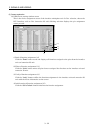
Connector
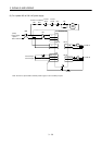
Model Maker
CNP1A
Housing: 1-178128-3 (X type)
Contact: 917511-2 (max. sheath OD: 2.8[mm] ( 0.11[in]))
353717-2 (max. sheath OD:
3.4[mm] ( 0.13[in])) (Note)
CNP1B
Housing: 2-178128-3 (Y type)
Contact: 917511-2 (max. sheath OD: 2.8[mm] ( 0.11[in]))
353717-2 (max. sheath OD:
3.4[mm] ( 0.13[in])) (Note)
CNP3
Housing: 1-179958-3
Contact: 316041-2
Tyco
Electronics
Note. This contact is not included in the option (MR-J2MCNM).