


12 - 14
12. OPTIONS AND AUXILIARY EQUIPMENT
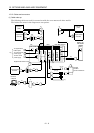
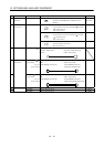
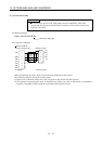
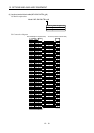
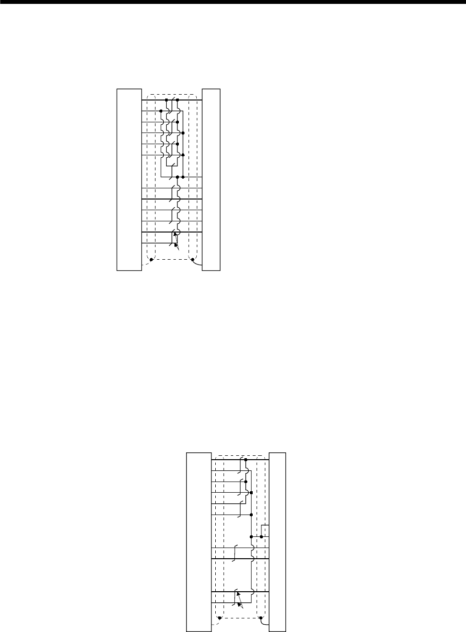
Note. Always make connection for use in an absolute position detection system.
This wiring is not needed for use in an incremental system.
P5
LG
P5
LG
19
11
20
12
2
MR
MRR
7
17
MDR 16 5
3
7
4
18P5
LG
MD 6
LG 1
BAT 9
SD
1
2
8
9
Drive unit side
Encoder side
Plate
(Note)
MR-JC4CBL30M-H
to
MR-JC4CBL50M-H
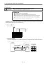
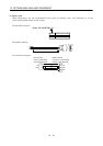
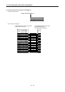
When fabricating an encoder cable, use the recommended wires given in Section 12.2.1 and the
MR-J2CNM connector set for encoder cable fabrication, and fabricate an encoder cable as shown
in the following wiring diagram. Referring to this wiring diagram, you can fabricate an encoder
cable of up to 50m(164.0ft) length.
When the encoder cable is to be fabricated by the customer, the wiring of MD and MDR is not
required.
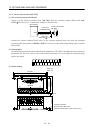
Refer to Chapter 3 of the servo motor instruction manual and choose the encode side connector
according to the servo motor installation environment.
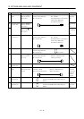
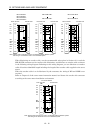
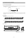
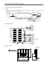
Note. Always make connection for use in an absolute position detection system.
This wiring is not needed for use in an incremental system.
19
11
20
12
18
2
P5
LG
P5
LG
P5
LG
7
17
9
1
MR
MRR
BAT
LG
SD
8
1
2
3
7
9
For use of AWG22
Drive unit side
Encoder side
Plate
(Note)
(3M)
6