


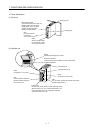
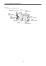
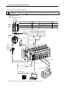
1 - 2
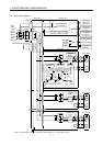
1. FUNCTIONS AND CONFIGURATION
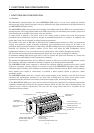
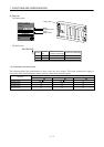
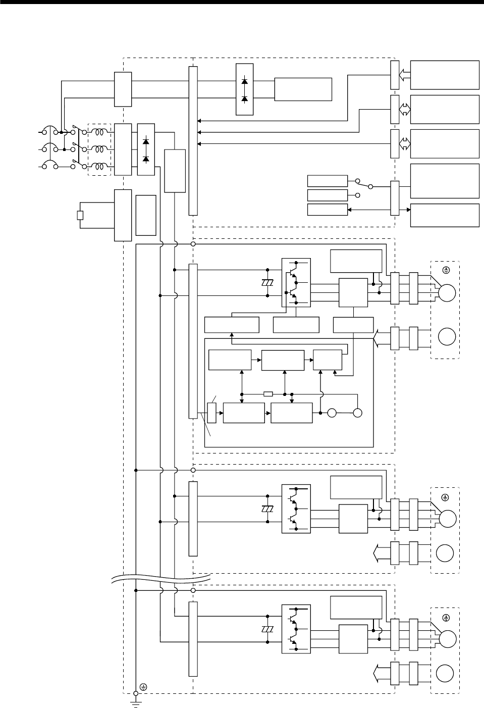
1.2 Function block diagram
W
RS-232C
D/A
NFB MC
W
V
U
L
11
L
21
L1
L
2
L
3
CNP3
CNP1B
P
N
C
CNP1A
U
V
M
CN1ACN1BCN3CNP2CN2CNP2CN2
W
U
V
M
CNP2CN2
FR-BAL
CN5
RS-422
CON3A-3H CON3A-3H CON3A-3H
Power
supply
3-phase
200 to
230VAC
(Note)
1-phase
200 to
230VAC
Base unit Interface unit
Analog monitor
(3 channels)
Regenerative brake option
Regener-
ative TR
Drive unit
Dynamic
brake
Servo motor
Inrush current
suppression
circuit
Current
detector
Actual position
control
Current
control
Model position
control
Model speed
control
Virtual
encoder
Virtual
servo
motor
Drive unit
Encoder
Drive unit
Dynamic
brake
Servo motor
Encoder
Current
detection
Dynamic
brake
Current
detection
Servo motor
Encoder
Model
position
Model
speed
Model
torque
Control circuit
power suppy
M
Overcurrent
protection
Current
detection
Base amplifie
r
Actual speed
control
Note. For 1-phase 200 to 230VAC, connect the power supply to L1, L2 and leave L3 open.
Pulse train position command
Pulse train position command
Input signal
Stroke end
Forced stop
I/O signals
for slots 1 to 4,
e.g. servo-on
I/O signals
for slots 5 to 8,
e.g. servo-on
Personal computer
or
other servo amplifier
Pulse train position command
Pulse
counter
(Earth)
(Earth)
(Earth)