


1 - 7
1. FUNCTIONS AND CONFIGURATION
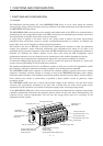
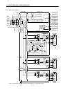
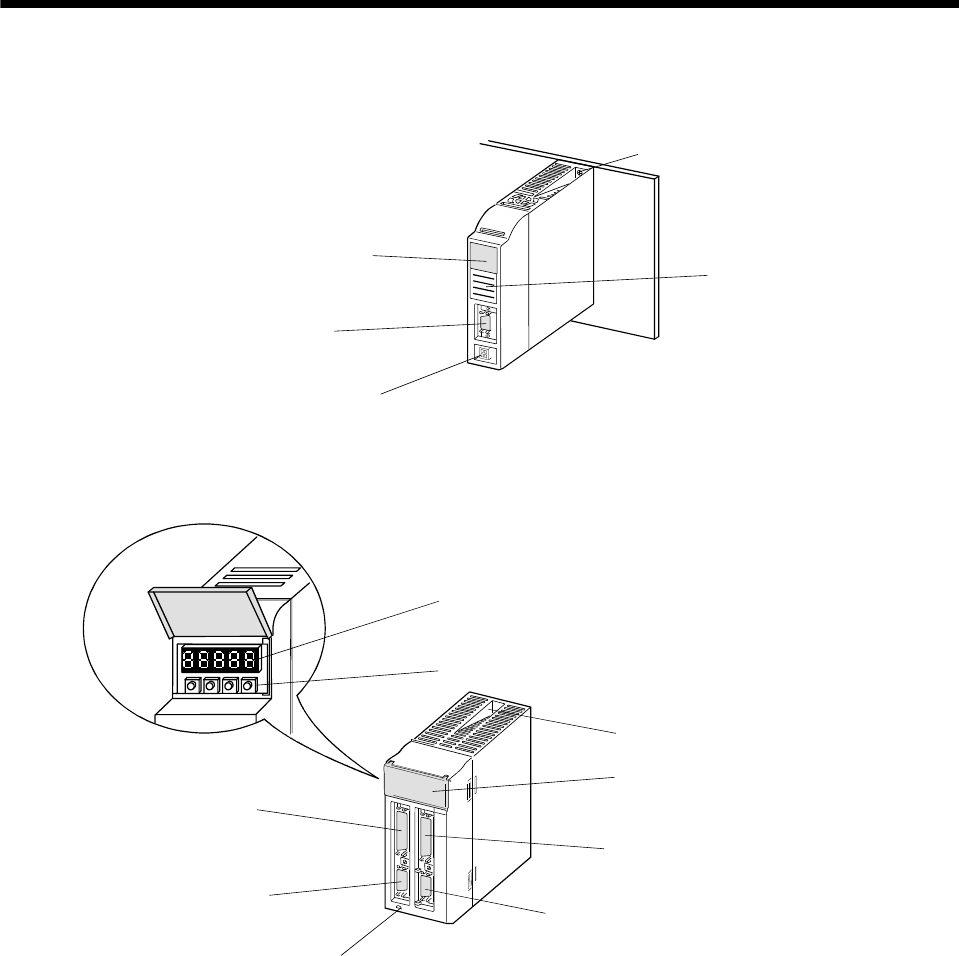
1.7 Parts identification
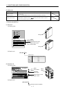
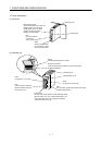
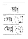
(1) Drive unit
Status indicator LED
Indicates the status of the drive unit.
Blinking green: Servo off status
Steady green: Servo on status
Blinking red: Warning status
Steady red: Alarm status
CN2
Encoder connector
Connect the
servo motor encoder
CNP2
Servo motor connector
For connection of servo
motor power line cable
Mounting screw
Rating plate
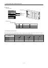
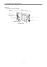
(2) Interface unit
Display
Indicates operating status or alarm.
CN1
A
I/O signal (For 1 to 4 slots)
CN3
For connection of personal computer (RS-232C).
Outputs analog monitor.
Pushbutton switches
Used to change status indication or set IFU parameters
and DRU parameters.
Mounting screw
Display/setting cover
CN1B
I/O signal (For 5 to 8 slots)
Charge lamp
Lit when main circuit capacitor carries electrical charge.
When this lamp is on, do not remove/reinstall any unit
from/to base unit and do not unplug/plug cable and
connector from/into any unit.
CN5
Forward rotation stroke end
Reverse rotation stroke end
Forced stop input