


3 - 23
3. SIGNALS AND WIRING
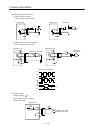
3.3.3 Signal explanations
For the IO interfaces (system in I/O column in the table), refer to section 3.2.5.
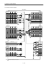
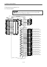
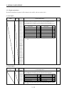
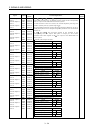
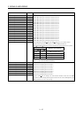
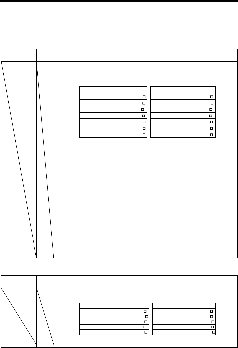
(1) Input signal
Signal Symbol
Connector
pin No.
Functions/Applications
I/O
division
CN4A-1
CN4A-2
CN4A-3
CN4A-4
No signals are factory-assigned to these pins. Using the MR Configurator
(servo configuration software), you can assign the input devices for
corresponding slots as signals. Refer to Section 3.3.4 for assignable devices.
CN4A-5
Device Name Symbol Device Name Symbol
CN4A-6
Servo-on SON Forward rotation stroke end LSP
CN4A-7
Reset RES Reverse rotation stroke end LSN
CN4A-8
Proportion control PC Clear CR
CN4A-26
Internal torque limit selection TL1 (Note) External torque limit TL
CN4A-27
Electronic gear selection 1 CM1 (Note) Speed selection 1 SP1
CN4A-28
Electronic gear selection 2 CM2 (Note) Speed selection 2 SP2
CN4A-29
Gain switching selection CDP (Note) Speed selection 3 SP3
CN4A-30
CN4A-31
CN4A-32
CN4A-33
CN4B-1
CN4B-2
CN4B-3
CN4B-4
CN4B-5
CN4B-6
CN4B-7
CN4B-8
CN4B-26
CN4B-27
CN4B-28
CN4B-29
CN4B-30
CN4B-31
CN4B-32
CN4B-33
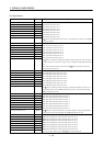
Note. You cannot select these devices when using the MR-J2M-P8A interface
unit.
DI-1
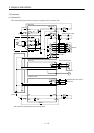
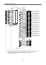
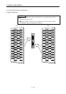
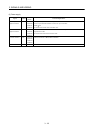
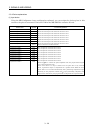
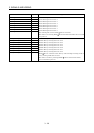
(2) Output signal
Signal Symbol
Connector
pin No.
Functions/Applications
I/O
division
No signals are factory-assigned to these pins. Using the MR Configurator
(servo configuration software), you can assign the input devices for
corresponding slots as signals. Refer to Section 3.3.4 for assignable devices.
DO-1
Device Name Symbol Device Name Symbol
Ready
RD
Limiting torque TLC
Electromagnetic brake interlock MBR
(Note) Limiting speed
VLC
In position INP Trouble ALM_
(Note) Up to speed
SA
Warning WNG
Zero speed detection ZSP Battery warning BWNG
CN4A-9
CN4A-10
CN4A-34
CN4A-35
CN4B-9
CN4B-10
CN4B-34
CN4B-35
Note. You cannot select these devices when using the MR-J2M-P8A interface
unit.