


4 - 14
4. OPERATION AND DISPLAY
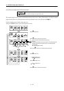
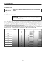
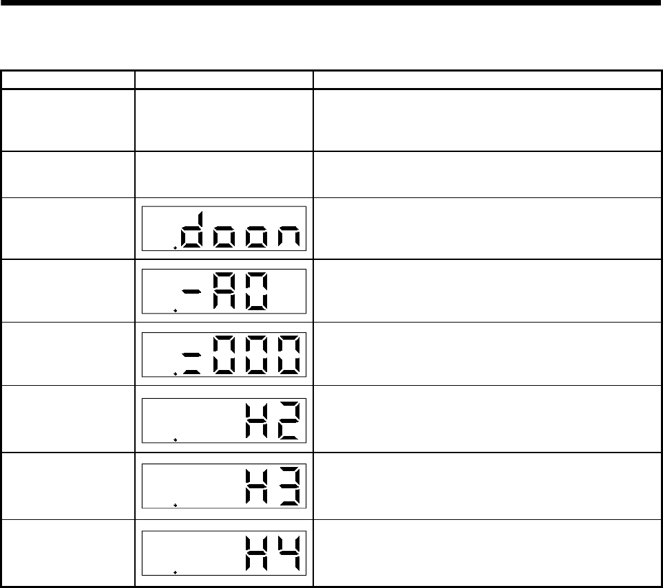
4.3.3 Diagnostic mode of drive unit
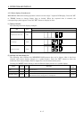
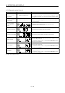
Name (Note) Display Description
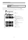
Drive unit external
input signal
Refer to section 4.3.6.
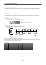
Shows the ON/OFF statuses of the external input signals.
Each signal corresponds to the function assignment. (The
corresponding segment is lit when the function-assigned signal
turns on.)
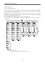
Drive unit external
output signal
Refer to section 4.3.6.
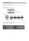
Shows the ON/OFF statuses of the external output signals.
When the corresponding segment is lit, the output is provided to
the assigned signal.
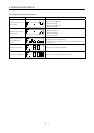
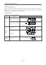
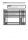
Drive unit output
signal (DO) forced
output
@
The digital output signal can be forced on/off. For more
information, refer to section 4.3.8.
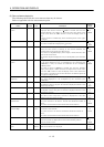
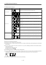
Software version Low
@
Indicates the version of the drive unit software.
Software version High
@
Indicates the system number of the drive unit software.
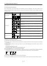
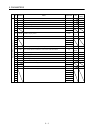
Motor series ID
@
Press the "SET" button to show the motor series ID of the servo
motor currently connected.
For indication details, refer to the optional MELSERVO Servo
Motor Instruction Manual.
Motor type ID
@
Press the "SET" button to show the motor type ID of the servo
motor currently connected.
For indication details, refer to the optional MELSERVO Servo
Motor Instruction Manual.
Encoder ID
@
Press the "SET" button to show the encoder ID of the servo motor
currently connected.
For indication details, refer to the optional MELSERVO Servo
Motor Instruction Manual.
Note. @ indicates the slot number.