


9 - 6
9. TROUBLESHOOTING
9.3 Remedies for alarms
CAUTION
When any alarm has occurred, eliminate its cause, ensure safety, then reset the
alarm, and restart operation. Otherwise, injury may occur.
If an absolute position erase (A.25) occurred, always make home position setting
again. Otherwise, misoperation may occur.
As soon as an alarm occurs, turn off Servo-on (SON ) and power off the main
circuit.
POINT
When any of the following alarms has occurred, always remove its cause
and allow about 30 minutes for cooling before resuming operation. If
operation is resumed by switching control circuit power off, then on to reset
the alarm, each unit and servo motor may become faulty.
Regenerative error (A.30) Overload 2 (A.51)
Overload 1 (A.50)
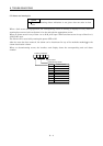
The alarm can be deactivated by switching power off, then on press the
“SET” button on the interface unit current alarm screen or by turning on
the reset (RES
). For details, refer to Section 9.2.
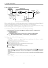
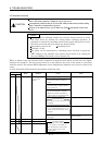
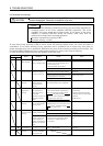
When an alarm occurs, the dynamic brake is operated to stop the servo motor. At this time, the display
indicates the alarm No. The servo motor comes to a stop. Remove the cause of the alarm in accordance
with this section. The optional MR Configurator (servo configuration software) may be used to refer to the
cause.
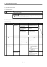
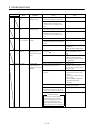
@ in the Indication field denotes the slot number of the base unit.
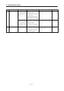
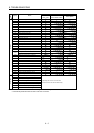
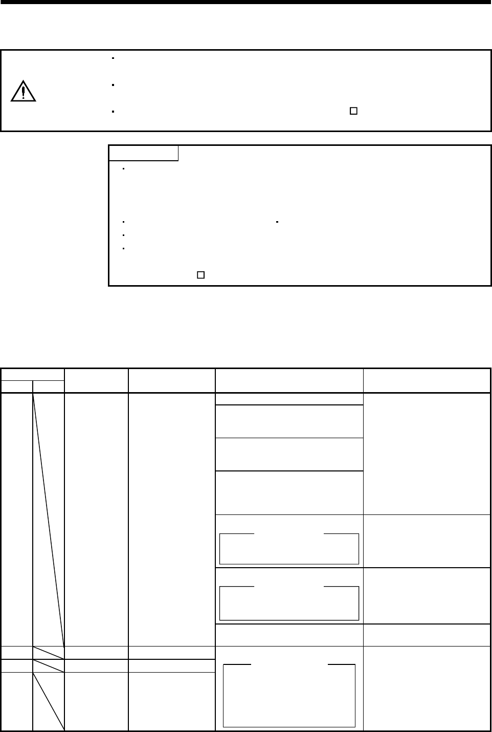
Display
IFU DRU
Name Definition Cause Action
1. Power supply voltage is low.
2. There was an instantaneous control
circuit power failure of 30ms or
longer.
3. Shortage of power supply capacity
caused the power supply voltage to
drop at start, etc.
4. Power was restored after the bus
voltage had dropped to 200VDC.
(Main circuit power switched on
within 5s after it had switched off.)
Review the power supply.
5. Faulty parts in the base unit.
Checking method
Alarm (A.10) occurs if interface unit
is changed.
Change the base unit.
6. Faulty parts in interface unit.
Checking method
Alarm (A.10) occurs if base unit is
changed.
Change the interface unit.
FA.10 Undervoltage Power supply voltage
fell to or below
160VAC.
7. CNP3 or CNP1B connector
unplugged.
Connect properly.
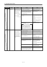
FA.12 Memory error 1 RAM, memory fault
FA.13 Clock error Printed board fault.
FA.15 Memory error 2 EEP-ROM fault
Faulty parts in the interface unit.
Checking method
Alarm (any of A.11 and 13)
occurs if power is switched on
after disconnection of all cables
but the control circuit power
supply cables.
Change the interface unit.