


4 - 5
4. OPERATION AND DISPLAY
4.2 Interface unit display
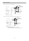
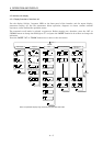
4.2.1 Display flowchart of interface unit
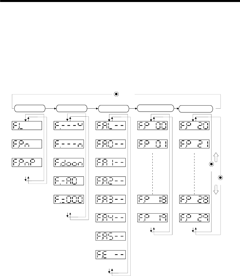
Use the display (5-digit, 7-segment LED) on the front panel of the interface unit for status display,
parameter setting, etc. Set the parameters before operation, diagnose an alarm, confirm external
sequences, and/or confirm the operation status.
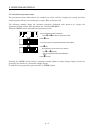
The automatic scroll mode is selected at power-on. Before starting use, therefore, press the "UP" or
"DOWN" button to change the fifth digit to "F" and press the "MODE" button for 2s or more to change the
indication.
Press the "MODE" "UP" or "DOWN" button once to move to the next screen.
UP
DOWN
MODE
button
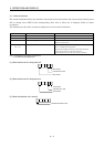
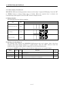
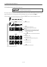
Status display Diagnosis
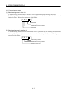
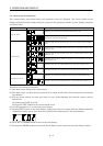
Alarm
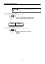
Basic IFU parameters
Regenerative load
ratio [%]
Current alarm
IFU parameter No. 0
IFU parameter No. 20
Bus voltage [V]
Last alarm
Second alarm in past
Third alarm in past
Fourth alarm in past
Fifth alarm in past
Sixth alarm in past
Parameter error No.
IFU parameter No. 19
IFU parameter No. 18
IFU parameter No. 1
IFU parameter No. 21
IFU parameter No. 28
IFU parameter No. 29
Software version
High
Software version
Low
Peak bus voltage
[V]
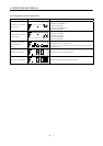
Interface unit
external input signa
l
Interface unit
external output signa
l
Expansion IFU
parameters
Interface unit output
signa
l (DO) forced output
Note. The parameter display range varies with the parameter write inhibit.