5 - 25
5. PARAMETERS
5.3.2 Analog monitor
The servo status can be output to 3 channels in terms of voltage. Using an ammeter enables monitoring
the servo status.
(1) Setting
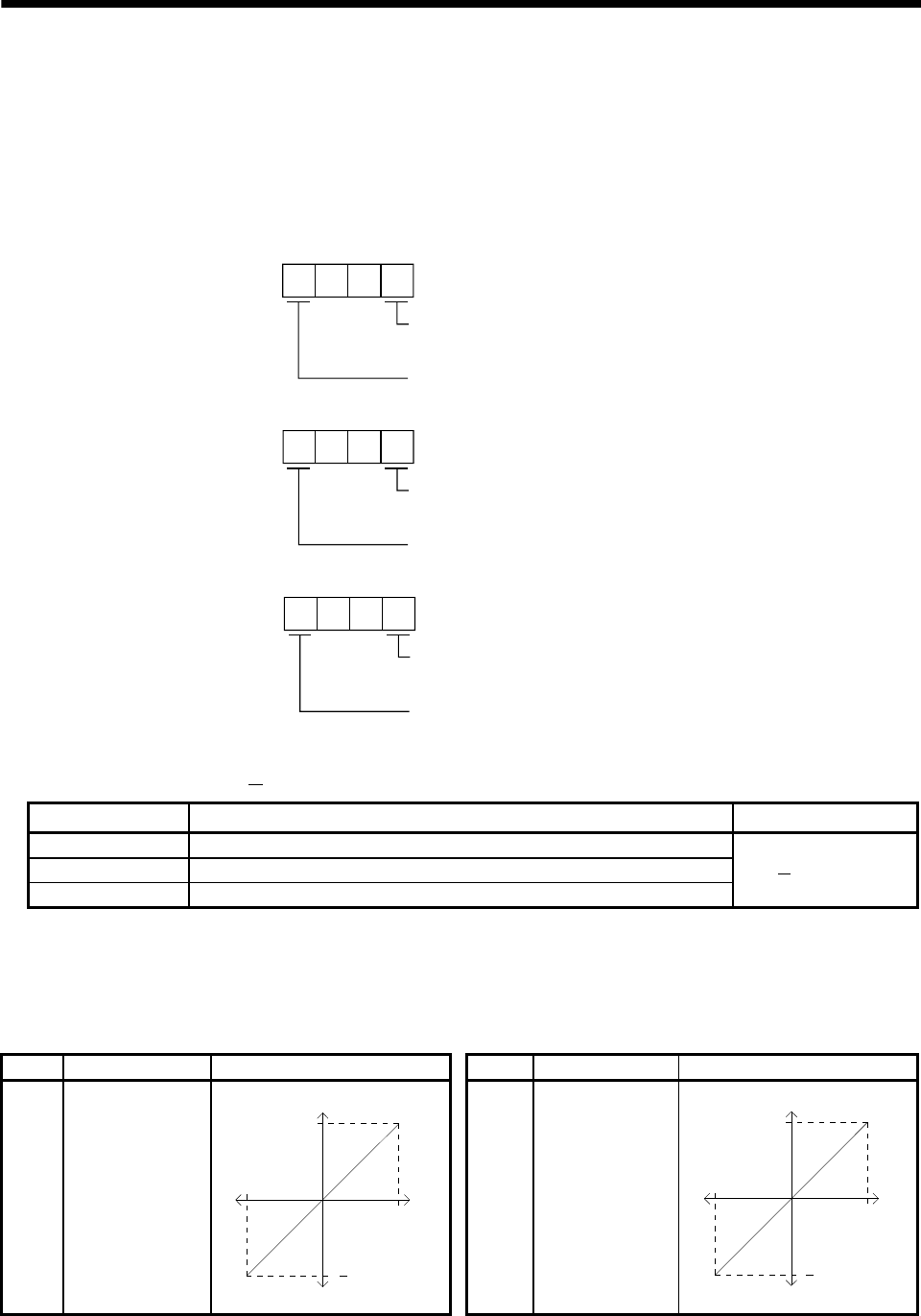
Change the following digits of IFU parameter No.3 to 5:
IFU parameter No. 3
Analog monitor 1 selection
(Signal output to across MO1-LG)
Slot number of analog monitor 1
IFU parameter No. 4
Analog monitor 2 selection
(Signal output to across MO2-LG)
Slot number of analog monitor 2
IFU parameter No. 5
Analog monitor 3 selection
(Signal output to across MO3-LG)
Slot number of analog monitor 3
IFU parameters No.6 to 8 can be used to set the offset voltages to the analog output voltages. The
setting range is between
999 and 999mV.
IFU parameter No. Description
Setting range [mV]
6 Used to set the offset voltage for the analog monitor 1.
7 Used to set the offset voltage for the analog monitor 2.
8 Used to set the offset voltage for the analog monitor 3.
999 to 999
(2) Settings
The three channels are all factory-set to output servo motor speeds. By changing the IFU parameter
No. 3 to 5 values, you can change the data as shown in the following tale.
Refer to (3) for measurement points.
Setting Output item Data Setting Output item Data
0 Servo motor speed
4[V]
0
4[V]
CCW direction
Max. speed
Max. speed
CW direction
1 Torque (Note)
4[V]
0
Driving in
CCW direction
Max. torque
Max. torque
Driving in
CW direction
4[V]


