


3 - 40
3. SIGNALS AND WIRING
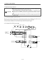
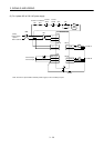
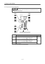
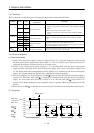
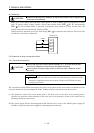
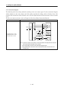
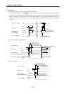
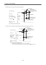
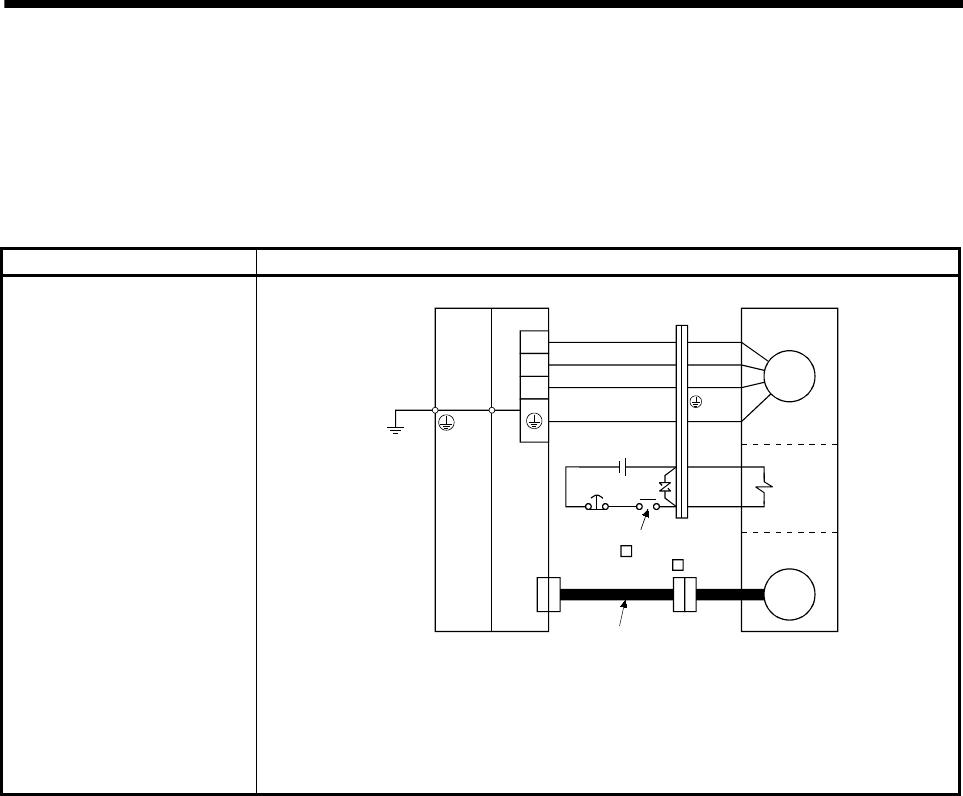
3.5.2 Connection diagram
The following table lists wiring methods according to the servo motor types. Use the connection diagram
which conforms to the servo motor used. For cables required for wiring, refer to Section 12.2.1. For
encoder cable connection, refer to Section 12.1.2. For the signal layouts of the connectors, refer to Section
3.5.3.
For the servo motor connector, refer to Chapter 3 of the Servo Motor Instruction Manual.
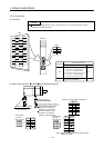
Servo motor Connection diagram
HC-KFS053 (B) to 73 (B)
HC-MFS053 (B) to 73 (B)
HC-UFS13 (B) to 73 (B)
U
V
W
EM1
B1
B2
CNP2
CN2
24VDC
(Note 1)
Encoder
Electro-
magnetic
brake
To be shut off when servo-
on (SON ) switches off or
by trouble (ALM_ )
Encoder cable
Motor
Servo motor
(Note 2)
(Note 3)
U (Red)
V (White)
W (Black)
(Green)
Base unit Drive unit
(Earth)
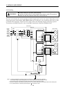
Note 1. To prevent an electric shock, always connect the protective earth (PE) terminal of the base
unit to the protective earth (PE) of the control box.
2. This circuit applies to the servo motor with electromagnetic brake.
3. The protective earth of the servo motor is connected to the base unit via the drive unit
mounting screw.