


3 - 35
3. SIGNALS AND WIRING
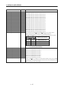
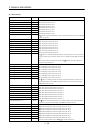
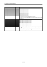
3.4 Signals and wiring for base unit
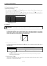
CAUTION
When each unit has become faulty, switch power off on the servo amplifier power
side. Continuous flow of a large current may cause a fire.
Use the trouble (ALM_
)
to switch power off. Otherwise, a regenerative brake
transistor fault or the like may overheat the regenerative brake resistor, causing a
fire.
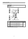
Fabricate the cables noting the shapes of the CNP1A housing (X type) and CNP1B
housing (Y type).
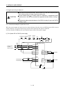
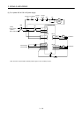
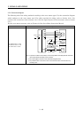
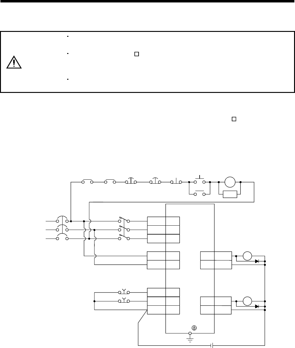
3.4.1 Connection example for power line circuit
Wire the power supply and main circuit as shown below so that the servo-on (SON
)
turns off as soon as
alarm occurrence, or a servo forced stop is made valid is detected and power is shut off.
A no-fuse breaker (NFB) must be used with the input cables of the power supply.
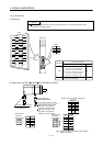
(1) For 3-phase 200 to 230VAC power supply
RA1
SG
EMG_A
EMG_B
20
19
8
MC
OFF
ON
MC
SK
MELSERVO-J2M
CNP3
CNP1B
RA2
MC
1
2
L11
L
21
1
2
L
1
L2
3L3
VIN
27
26
ALM_B
VIN
27
26
ALM_A
CN5
CN1A
CN1B
NFB
Power supply
3-phase
200 to 230VAC
Trouble A
Trouble B
Forced
stop A
Forced
stop B
RA1
Trouble
A
Trouble B
RA2
24VDC
Forced stop A
Forced stop B