


3 - 2
3. SIGNALS AND WIRING
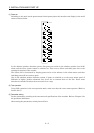
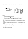
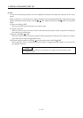
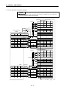
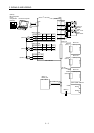
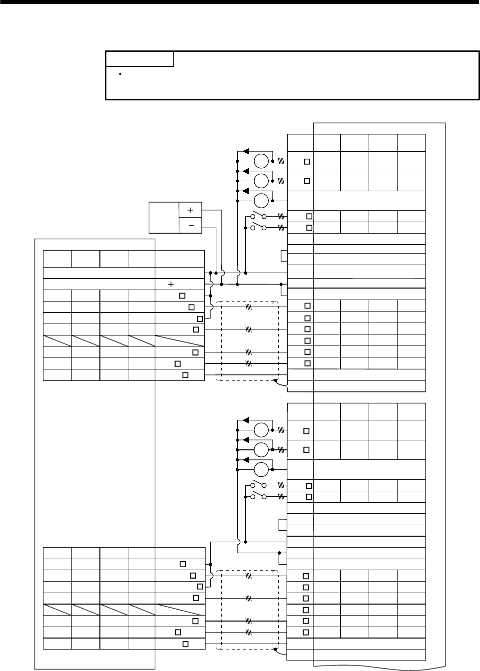
3.1 Control signal line connection example
POINT
Refer to Section 3.4 for connection of the power supply line and to Section
3.5 for connection with servo motors.
SON
CR
RES
SG
VIN
OPC
RD
ALM_B
INP
LG
P5
OP_VIN
PG
PP
NP
NG
OP
SD
LG
SON
CR
RES
SG
VIN
OPC
P5
OP_VIN
PG
PP
NP
NG
OP
SD
37
36
PULSE F
24G
PULSE COM
29
4
CN1A(Note 4)
1
MR-J2M-P8A
37
12
10
34
9
32
7
31
5
36
26
2
11 33 6 28RD
358303
ALM_A
INP
27
49
47
48
3844 42 40
1319 17 15
1420 18 16
3945 43 41
2225 24 23
A7A4B7B4
A1
A15A13B15B13
B1
RA
RA
RA
A16A14B16B14
A6A3B6B3
29
4
1
12
10
34
9
32
7
31
5
26
2
11 33 6
28
358303
27
49
47
48
3844 42 40
1319 17 15
1420 18 16
3945 43 41
2225 24 23
A7
PULSE F
A4B7B4
A5
PULSE R
A2B5B2
A15
CLEAR
A13B15B13
A16
CLEAR COM
A14B16B14
PULSE COM
A6A3B6B3
RA
RA
RA
CON1
Positioning module
QD70
Slot 1 Slot 2 Slot 3 Slot 4
Slot 1 Slot 2 Slot 3 Slot 4
Slot 5 Slot 6 Slot 7 Slot 8
Slot 5 Slot 6 Slot 7 Slot 8
24VDC
power
supply
(Note 13)
Symbol
24V
CLEAR COM
CLEAR
Symbol
Plate
(Note 8)
(Note 7)
(Note 2)
(Note 13) CN1B(Note 4)
Symbol
Symbol
Plate
21, 46, 50
21, 46, 50
(Note 8)
(Note 7)
(Note 2)
(Note 13)
B18
B17 B19
B20 A18
A17 A19
PG COM
PG
A20
B18
B17 B19
B20 A18
A17 A19
PG COM
PG
A20
B2 B5
A2 A5
PULSE R
OP_COM
OP_COM
CON2 (Note 13)