


3 - 16
3. SIGNALS AND WIRING
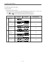
3.2.5 Interface
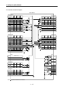
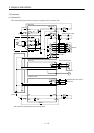
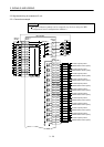
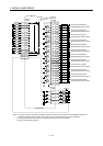
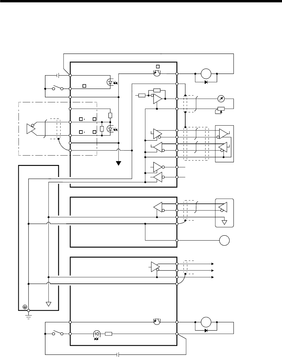
(1) Common line
The following diagram shows the power supply and its common line.
PG NG
MR
OPC
SD
SG
LG
SD
SG
VIN
24VDC
DI-1
RA
SDP
SDN
RDP
RDN
LG
TXD
RXD
RS-232C
MRR
LG
SD
M
E
LG
SD
SG
EM1
DI-1
RA
VIN
MBR
RS-422
24VDC
Interface unit
(Note)
Analog monitor output
INP , etc.
Base unit
Drive unit
Servo motor encoder
Servo motor
Differential line driver outpu
t
Extension IO unit
Ground
SON , etc.
PG NP
MO3
MO1
MO2
LA, etc.
LAR, etc.
35mA max.
Note. Assumes a differential line driver pulse train input.