


3 - 8
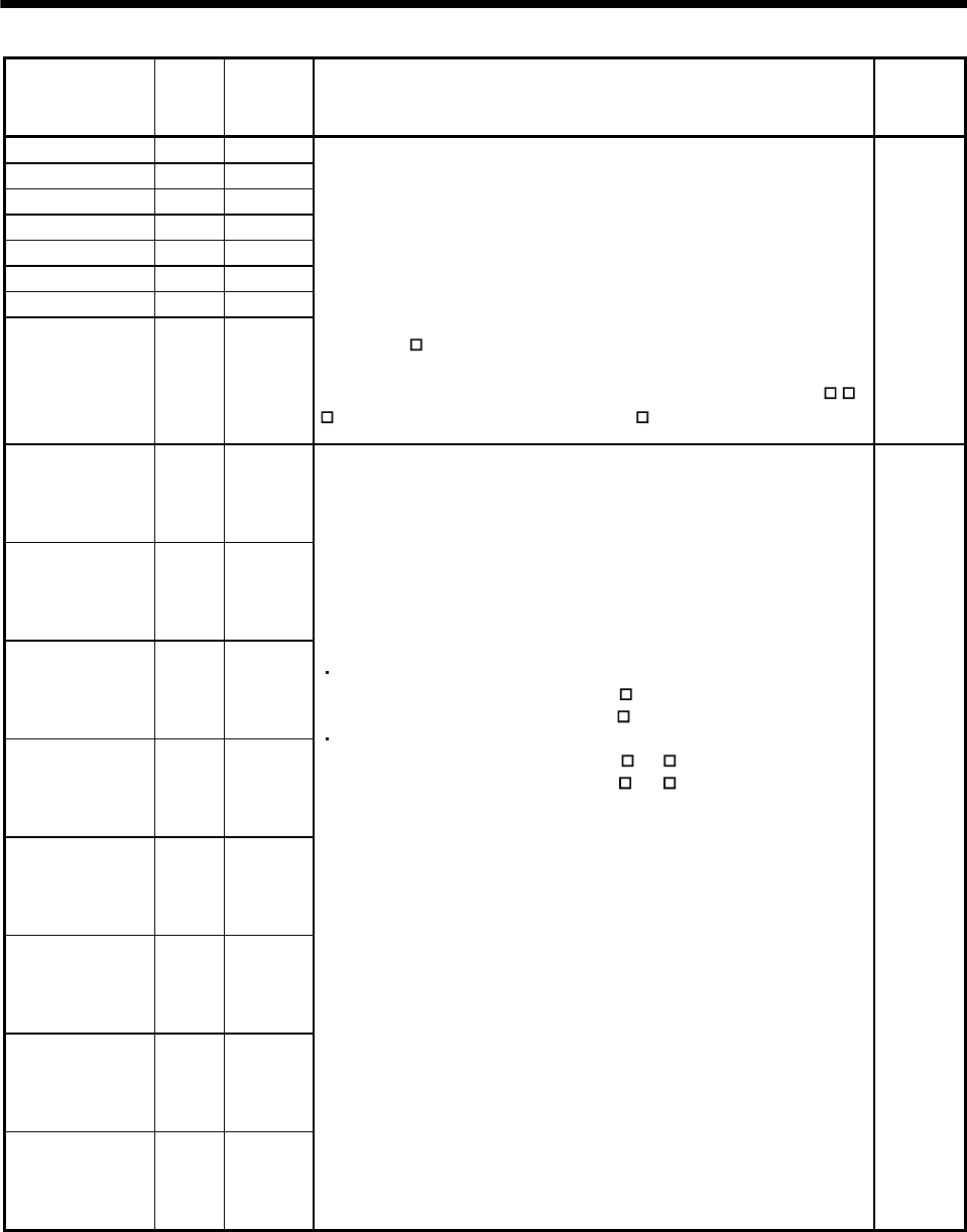
3. SIGNALS AND WIRING
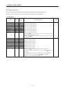
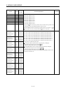
Signal Symbol
Connector
pin No.
Functions/Applications I/O division
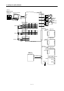
Clear 1 CR 1 CN1A-12
Clear 2 CR 2 CN1A-34
Clear 3 CR 3 CN1A-7
Clear 4 CR 4 CN1A-29
Clear 5 CR 5 CN1B-12
Clear 6 CR 6 CN1B-34
Clear 7 CR 7 CN1B-7
Clear 8 CR 8 CN1B-29
CR 1: Clear signal for slot 1
CR 2: Clear signal for slot 2
CR 3: Clear signal for slot 3
CR 4: Clear signal for slot 4
CR 5: Clear signal for slot 5
CR 6: Clear signal for slot 6
CR 7: Clear signal for slot 7
CR 8: Clear signal for slot 8
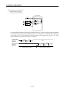
Connect CR
-SG to clear the position control counter droop pulses on its
leading edge. The pulse width should be 10ms or more.
When the DRU parameter No.42 (Input signal selection 1) setting is "
1
", the pulses are always cleared while CR -SG are connected.
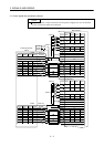
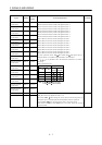
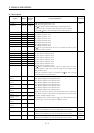
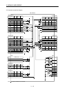
DI-1
Forward rotation
pulse train 1
Reverse rotation
pulse train 1
PP 1
NP 1
PG 1
NG 1
CN1A-19
CN1A-20
CN1A-44
CN1A-45
Forward rotation
pulse train 2
Reverse rotation
pulse train 2
PP 2
NP 2
PG 2
NG 2
CN1A-17
CN1A-18
CN1A-42
CN1A-43
Forward rotation
pulse train 3
Reverse rotation
pulse train 3
PP 3
NP 3
PG 3
NG 3
CN1A-15
CN1A-16
CN1A-40
CN1A-41
Forward rotation
pulse train 4
Reverse rotation
pulse train 4
PP 4
NP 4
PG 4
NG 4
CN1A-13
CN1A-14
CN1A-38
CN1A-39
Forward rotation
pulse train 5
Reverse rotation
pulse train 5
PP 5
NP 5
PG 5
NG 5
CN1B-19
CN1B-20
CN1B-44
CN1B-45
Forward rotation
pulse train 6
Reverse rotation
pulse train 6
PP 6
NP 6
PG 6
NG 6
CN1B-17
CN1B-18
CN1B-42
CN1B-43
Forward rotation
pulse train 7
Reverse rotation
pulse train 7
PP 7
NP 7
PG 7
NG 7
CN1B-15
CN1B-16
CN1B-40
CN1B-41
Forward rotation
pulse train 8
Reverse rotation
pulse train 8
PP 8
NP 8
PG 8
NG 8
CN1B-13
CN1B-14
CN1B-38
CN1B-39
PP 1 NP 1 PG 1 NG 1: Forward/reverse rotation pulse train for slot 1
PP 2 NP 2 PG 2 NG 2: Forward/reverse rotation pulse train for slot 2
PP 3 NP 3 PG 3 NG 3: Forward/reverse rotation pulse train for slot 3
PP 4 NP 4 PG 4 NG 4: Forward/reverse rotation pulse train for slot 4
PP 5 NP 5 PG 5 NG 5: Forward/reverse rotation pulse train for slot 5
PP 6 NP 6 PG 6 NG 6: Forward/reverse rotation pulse train for slot 6
PP 7 NP 7 PG 7 NG 7: Forward/reverse rotation pulse train for slot 7
PP 8 NP 8 PG 8 NG 8: Forward/reverse rotation pulse train for slot 8
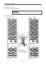
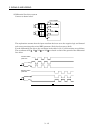
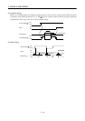
Used to enter a command pulse train.
In the open collector system (max. input frequency 200kpps):
Forward rotation pulse train across PP
-SG
Reverse rotation pulse train across NP
-SG
In the differential receiver system (max. input frequency 500kpps):
Forward rotation pulse train across PG
-PP
Reverse rotation pulse train across NG -NP
The command pulse train form can be changed using DRU parameter No.
21 (Function selection 3).
DI-2