


3 - 38
3. SIGNALS AND WIRING
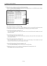
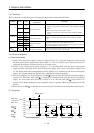
3.4.3 Terminals
Refer to Section 10.2 for the layouts and signal configurations of the terminal blocks.
Connector Pin No. Code
Connection target
(Application)
Description
1L
1
2L
2
CNP3
3L
3
Main circuit power
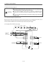
(1) When using a three -phase power supply
Supply L
1
, L
2
and L
3
with three-phase, 200 to 230VAC, 50/60Hz
power.
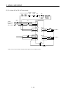
(2) When using a signal -phase power supply
Supply L
1
and L
2
with signal-phase, 200 to 230VAC, 50/60Hz
power.
1L
11
2L
21
CNP1B
3
Control circuit power
Supply L
11
and L
21
with single-phase, 200 to 230VAC, 50/60Hz
power.
1N
2P
CNP1A
3C
Regenerative brake
option
Connect the regenerative brake option across P-C.
Accidental connection of the regenerative brake option to P-N may
cause burning (Refer to Section 12.1.1)
(Earth)
Protective earth (PE)
Connect this terminal to the protective earth (PE) terminals of the
servo motor and control box for grounding.
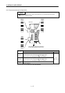
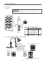
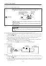
3.4.4 Power-on sequence
(1) Power-on procedure
1) Always wire the power supply as shown in above Section 3.7.1 using the magnetic contactor with
the main circuit power supply (three-phase 200V: L
1, L2, L3). Configure up an external sequence to
switch off the magnetic contactor as soon as an alarm occurs.
2) Switch on the control circuit power supply L
11
, L
21
simultaneously with the main circuit power
supply or before switching on the main circuit power supply. If the main circuit power supply is not
on, the display shows the corresponding warning. However, by switching on the main circuit power
supply, the warning disappears and the servo amplifier will operate properly.
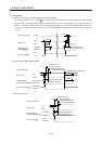
3) The servo amplifier can accept the servo-on (SON
) about 3s after the main circuit power supply is
switched on. Therefore, when SON
is switched on simultaneously with the main circuit power
supply, the base circuit will switch on in about 1 to 2s, and the ready (RD
) will switch on in
further about 20ms, making the servo amplifier ready to operate. (Refer to paragraph (2) in this
section.)
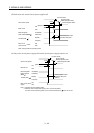
4) When the reset (RES
) is switched on, the base circuit is shut off and the servo motor shaft coasts.
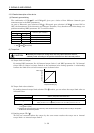
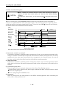
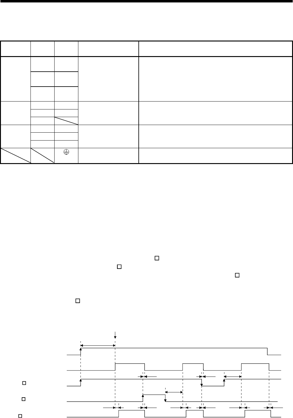
(2) Timing chart
100ms
100ms
OFF
ON
OFF
ON
ON
OFF
OFF
ON
OFF
ON
10ms20ms
10ms
10ms20ms
10ms
20ms 10ms
(3s)
SON accepted
Base circuit
Servo-on
(SON )
Reset
(RES )
Ready
(RD )
Main circui
t
control circuit
power