


13 - 2
13. COMMUNICATION FUNCTIONS
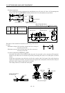
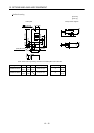
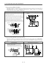
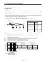
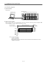
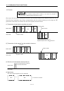
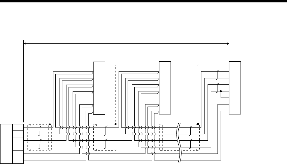
(2) Cable connection diagram
Wire as shown below:
RDP
RDN
SDP
SDN
GND
GND
5
15
9
19
11
1
10
RDP
RDN
SDP
SDN
LG
LG
TRE
SD
5
15
9
19
11
1
10
RDP
RDN
SDP
SDN
LG
LG
TRE
SD
5
15
9
19
11
1
10
RDP
RDN
SDP
SDN
LG
LG
TRE
SD
(Note 3) 30m(98.4ft) max.
Plate
(Note 1)
Interface unit or Servo amplifier
CN3 connector
Plate
Plate
(Note 2)
RS-422
output unit
(Note 1)
Interface unit or Servo amplifier
CN3 connector
(Note 1)
Interface unit or Servo amplifie
r
CN3 connector
Note 1. Connector set MR-J2CN1 (3M or equivalent)
Connector: 10120-3000VE
Shell kit: 10320-52F0-008
2. In the last axis, connect TRE and RDN.
3. 30m (98.4ft) max. in environment of little noise.