


3 - 27
3. SIGNALS AND WIRING
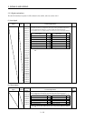
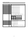
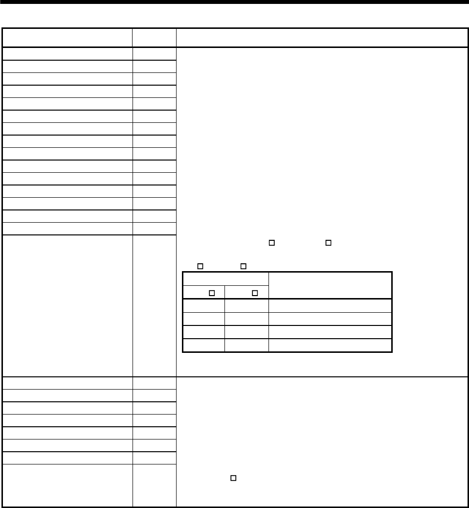
Device name Symbol Functions/Applications
Electronic gear selection 11 CM11
Electronic gear selection 12 CM12
Electronic gear selection 13 CM13
Electronic gear selection 14 CM14
Electronic gear selection 15 CM15
Electronic gear selection 16 CM16
Electronic gear selection 17 CM17
Electronic gear selection 18 CM18
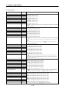
Electronic gear selection 21 CM21
Electronic gear selection 22 CM22
Electronic gear selection 23 CM23
Electronic gear selection 24 CM24
Electronic gear selection 25 CM25
Electronic gear selection 26 CM26
Electronic gear selection 27 CM27
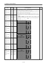
CM11: Electronic gear selection 1 device for slot 1
CM12: Electronic gear selection 1 device for slot 2
CM13: Electronic gear selection 1 device for slot 3
CM14: Electronic gear selection 1 device for slot 4
CM15: Electronic gear selection 1 device for slot 5
CM16: Electronic gear selection 1 device for slot 6
CM17: Electronic gear selection 1 device for slot 7
CM18: Electronic gear selection 1 device for slot 8
CM21: Electronic gear selection 2 device for slot 1
CM22: Electronic gear selection 2 device for slot 2
CM23: Electronic gear selection 2 device for slot 3
CM24: Electronic gear selection 2 device for slot 4
CM25: Electronic gear selection 2 device for slot 5
CM26: Electronic gear selection 2 device for slot 6
CM27: Electronic gear selection 2 device for slot 7
CM28: Electronic gear selection 2 device for slot 8
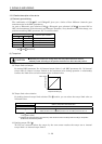
The combination of CM1
-SG and CM2 -SG gives you a choice of four
different electronic gear numerators set in the DRU parameters.
CM1
and CM2 cannot be used in the absolute position detection system.
(Note) Input signal
CM2 CM1
Electronic gear numerator
0 0 DRU parameter No.3
0 1 DRU parameter No.69
1 0 DRU parameter No.70
1 1 DRU parameter No.71
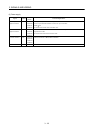
Electronic gear selection 28 CM28
Note. 0: Off across terminal-SG (open)
1: On across terminal-SG (shorted)
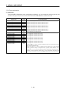
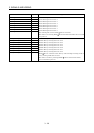
Gain switching 1 CDP1
Gain switching 2 CDP2
Gain switching 3 CDP3
Gain switching 4 CDP4
Gain switching 5 CDP5
Gain switching 6 CDP6
Gain switching 7 CDP7
Gain switching 8 CDP8
CDP1: Gain switching device for slot 1
CDP2: Gain switching device for slot 2
CDP3: Gain switching device for slot 3
CDP4: Gain switching device for slot 4
CDP5: Gain switching device for slot 5
CDP6: Gain switching device for slot 6
CDP7: Gain switching device for slot 7
CDP8: Gain switching device for slot 8
Connect CDP
-SG to change the load inertia moment ratio into the DRU
parameter No. 61 setting and the gain values into the values multiplied by the
DRU parameter No. 62 to 64 settings.