


3 - 39
3. SIGNALS AND WIRING
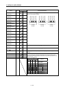
Device Symbol
Connector pin No.
Functions/Applications
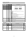
PT BCD
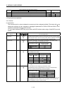
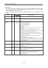
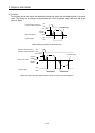
M code 1 (bit0) MCD00 CN10-38 As soon as Rough match (CPO) turns ON, the M code is output.
2nd digit
bit3 MCD13
bit2 MCD12
bit1 MCD11
bit0 MCD10
bit3 MCD03
bit2 MCD02
bit1 MCD01
bit0 MCD00
1st digit
MCD00 to MCD03 and MCD10 to MCD13 turn OFF in any of the following
statuses.
Power on
Servo off
During home position return
Home position return completion
In any of the following statuses, MCD00 to MCD03 and MCD10 to MCD13
maintain their pre-change status (ON/OFF).
When operation mode is changed
When Automatic/manual selection (MD0) is turned from OFF to ON or from ON
to OFF to change the operation mode.
During manual operation
During execution of automatic positioning to home position
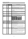
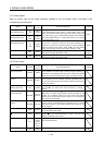
M code 2 (bit1) MCD01 CN10-39
M code 3 (bit2) MCD02 CN10-40
M code 4 (bit3) MCD03 CN10-41
M code 5 (bit4) MCD10 CN10-42
M code 6 (bit5) MCD11 CN10-43
M code 7 (bit6) MCD12 CN10-44
M code 8 (bit7) MCD13 CN10-45
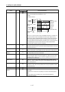
Position data request 1 PRQ1 CN10-44 PRQ0 is turned ON when the position data of symbol and sixth/fifth/fourth digits
are requested to a programmable controller during the positioning operation with
the BCD 3 digits
2 input.
Position data request 2 PRQ2 CN10-45 PRQ1 is turned ON when the position data of third/second/first digits are
requested to a programmable controller during the positioning operation with the
BCD 3 digits
2 input.
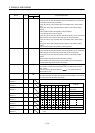
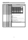
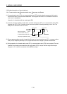
3.5.2 Input signals
Signal
Symbol Connector pin No.
Functions/Applications
I/O
division
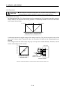
Manual pulse generator PP
CN6-6
Used to connect the manual pulse generator (MR-HDP01). (Refer to
section 13.18.)
NP
CN6-19
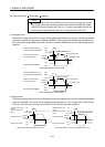
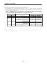
Analog torque limit TLA
CN20-12
When the analog torque limit (TLA) is valid, torque is limited in the full
servo motor output torque range. Apply 0 to +10VDC across TLA-LG.
Connect the positive terminal of the power supply to TLA. Maximum
torque is generated at +10V. (Refer to section 3.6.3.) Resolution: 12bit
Analog
input
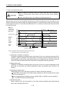
Override VC
CN20-2
By applying -10 to +10V across VC-LG, the servo motor speed is
limited.
The limit value is 0% with -10V, 100% with 0V and 200% with +10V to
the rated speed of the servo motor.
Analog
input