13 - 90
13. OPTIONS AN
D AUXILIARY EQUIPMENT
13.19 MR-DS60 6-digit digital switch
Using the MR-DS60 6-digit digital switch can send the position data in the BCD signal. For the connection of
MR-DS60 and MR-J3-D01, refer to section 3.2.2.
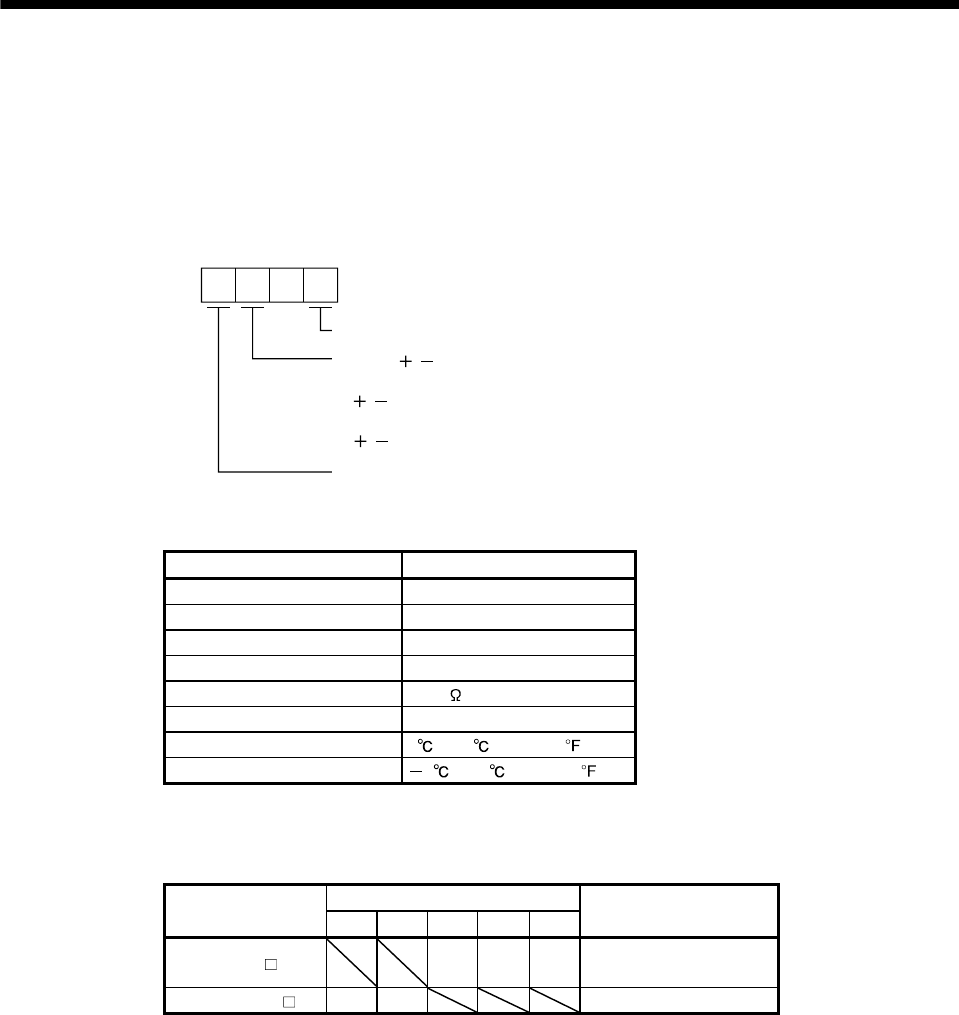
(1) Parameter setting
When using MR-DS60, set the parameter as shown below.
Positioning operation by BCD input.
20
Parameter No. Po10
2
Symbol ( / ) of the positioning data in the BCD positioning
0: Invalid
/ symbol is not used
1: Valid
/ symbols is used
Strobe signal invalid
(2) Specifications of MR-DS60
Item Specifications
Type MR-DS60A
Number of digits Signal 6-digit BCD
Electrical characteristic 28VDC (0.5A)
Dielectric withstand voltage 500Vr.m.s
Contact resistance 100m or less
Life 1,000,000 times
Operating temperature range 0 to 60 (32 to 140 )
Storage temperature range 5 to 70 (23 to 158 )
(3) Digital switch cable
Connect MR-DS60 to MR-J3-D01 with the digital switch cable indicated below.
Cable Model
Cable Length
Application
25cm 1m 3m 5m 10m
MS-DSCBL M-G 3 5 10
For between MR-DS60
and MR-J3B-D01
MR-DSCBL 25 100 For between MR-DS60s


