


3 - 68
3. SIGNALS AND WIRING
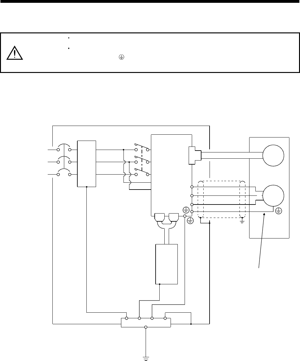
3.12 Grounding
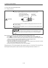
WARNING
Ground the servo amplifier and servo motor securely.
To prevent an electric shock, always connect the protective earth (PE) terminal
(terminal marked
) of the servo amplifier with the protective earth (PE) of the
control box.
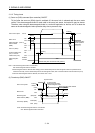
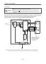
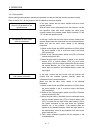
The servo amplifier switches the power transistor on-off to supply power to the servo motor. Depending on the
wiring and ground cable routing, the servo amplifier may be affected by the switching noise (due to di/dt and
dv/dt) of the transistor. To prevent such a fault, refer to the following diagram and always ground.
To conform to the EMC Directive, refer to the EMC Installation Guidelines (IB(NA)67310).
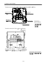
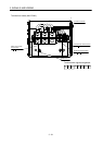
Control box
Servo amplifier
L
1
L2
L
3
L
11
L
21
CN1A
CN1B
Line filter
NFB
MC
Protective earth(PE)
CN2
U
V
W
Outer
box
Servo motor
Ensure to connect it to PE
terminal of the servo amplifier.
Do not connect it directly to
the protective earth of
the control panel.
Encoder
M
U
V
W
Programmable
controller
(Note)
Power supply
Note. For 1-phase 200V to 230VAC of 1-phase 100 to 120VAC, connect the power supply to L1, L2 and leave L3 open.
There is no L
3 for 1-phase 100 to 120VAC power supply. Refer to section 1.2 for the power supply specification.