


App. - 6
A
PPENDI
X
App. 4 MR-J3-200T-RT servo amplifier
Connectors (CNP1, CNP2, and CNP3) and appearance of MR-J3-200T servo amplifier have been changed
from June 2014 production. Model name of the existing servo amplifier is changed to MR-J3-200T-RT. The
difference between new MR-J3-200T servo amplifier and existing MR-J3-200T-RT servo amplifier is described
in this appendix. Sections within parentheses in the following sections indicate corresponding sections of the
instruction manual.
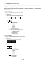
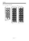
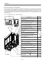
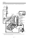
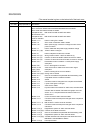
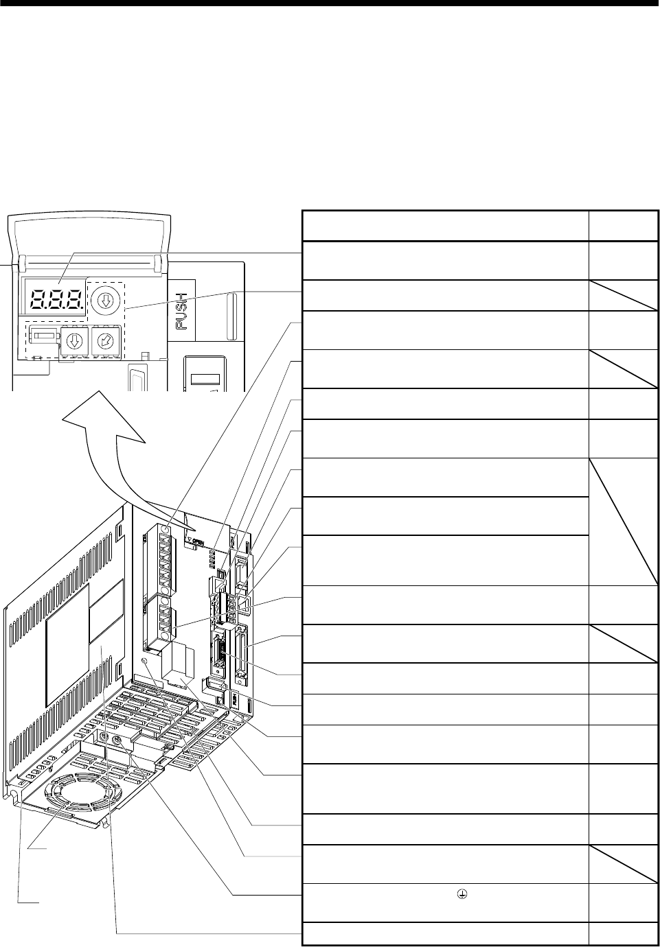
App. 4.1 Parts identification (1.6.1 Parts identification)
5
4
3
2
1
0
9
8
7
6
5
4
3
2
1
0
9
8
7
6
5
4
3
2
1
0
9
8
7
6
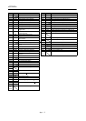
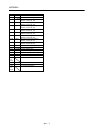
Name/Application
Detailed
Explanation
Section 4.3
Chapter 10
When using in combination with MR-J3-D01, do not
change the setting (default) shown in the figure.
Section 3.1
Section 3.3
Section 11.1
Communication alarm display section
When using in combination with MR-J3-D01, the LED
display does not have any meaning.
Chapter 6
Chapter 6
Chapter 7
Chapter 14
Analog input connector (CN20)
Used to connect the analog torque limit or override analog
input signal.
Digital display connector (CN30)
Used to connect the MR-DP60 digital display.
The MR-PRU03 parameter unit or a personal computer
cannot be connected.
Section 3.1
Section 3.3
Section 11.1
Fixed part
(3 places)
Section 1.4
Section 3.2
Section 3.4
Section 3.10
Section 13.1
Section 4.9
Section 13.7
Section 3.1
Section 3.3
Section 11.1
Section 13.2
Section 4.9
Section 3.1
Section 3.3
Section 11.1
CC-Link connector (CN1)
When using in combination with MR-J3-D01, this
connector is not used. Do not connect anything to it.
Protective earth (PE) terminal ( )
Ground terminal.
Charge lamp
Lit to indicate that the main circuit is charged. While this
lamp is lit, do not reconnect the cables.
Battery holder
Contains the battery for absolute position data backup.
Control circuit connector (CNP2)
Used to connect the control circuit power supply/
regenerative ption.
Battery connector (CN4)
Used to connect the battery for absolute position data
backup.
Encoder connector (CN2)
Used to connect the servo motor encoder.
I/O signal connector (CN6)
Used to connect digital I/O signals.
I/O signal connector (CN10)
Used to connect the digital I/O signal or analog output
signal.
Servo motor power connector (CNP3)
Used to connect the servo motor.
RS-422 communication connector (CN3)
Used to connect the MR-PRU03 parameter unit or
personal computer.
USB communication connector (CN5)
Used to connect the personal computer.
Main circuit power supply connector (CNP1)
Used to connect the input power supply.
Display
The 3-digit, seven-segment LED shows the servo status
and alarm number.
Rating plate
Cooling fan