


5 - 42
5. PARAMETERS
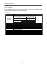
No. Symbol Name and function
Initial
value
Unit
Setting
range
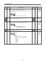
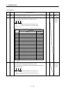
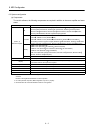
Po11 For manufacturer setting
Do not change this value by any means.
0000h
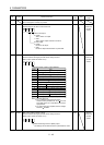
Po12 *OOP3 Function selection O-3
Set the output of the alarm code and M code.
Alarm code output
0: Invalid
Alarm code is not output.
1: Valid
Alarm code is output at alarm occurrence.
M code output
0: Invalid
M code is not output.
1: Valid
M code is output after execution of point table.
00
0000h Refer to
name and
function
column.
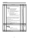
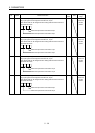
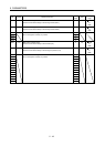
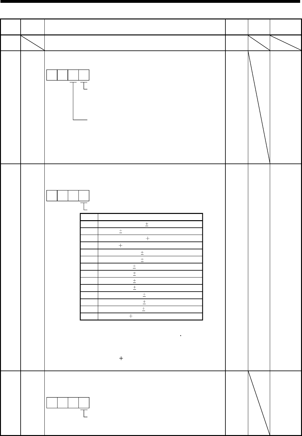
Po13 MOD1 MR-J3-D01 analog monitor 1 output
Used to selection the signal provided to the analog monitor 1
(MO1) output. (Refer to section 6.5.3.)
Note 1. Encoder pulse unit.
2. 8V is outputted at the maximum torque.
However, when parameter No. PA11 PA12 are
set to limit torque, 8V is outputted at the torque
highly limited.
3. For 400V class servo amplifier, the bus voltage
becomes 8V/800V.
C
B
000
Setting
0
Item
Servo motor speed ( 8V/max. speed)
1
2
3
4
5
Speed command ( 8V/max. speed)
6
7
8
9
A
D
Analog monitor 1 (MO1) output selection
Torque ( 8V/max. torque) (Note 2)
Servo motor speed ( 8V/max. speed)
Torque ( 8V/max. torque) (Note 2)
Current command ( 8V/max. current command)
Droop pulses ( 10V/100 pulses) (Note 1)
Droop pulses ( 10V/1000 pulses) (Note 1)
Droop pulses ( 10V/10000 pulses) (Note 1)
Droop pulses ( 10V/100000 pulses) (Note 1)
Feedback position ( 10V/1 Mpulses) (Note 1)
Feedback position ( 10V/10 Mpulses) (Note 1)
Feedback position ( 10V/100 Mpulses) (Note 1)
Bus voltage ( 8V/400V) (Note 3)
0000h Refer to
name and
function
column.
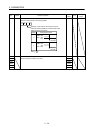
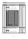
Po14 MOD2 MR-J3-D01 analog monitor 2 output
Used to selection the signal provided to the analog monitor 2
(MO2) output. (Refer to section 5.5.3.)
000
Select the analog monitor 2 (MO2) output
The settings are the same as those of parameter No. Po13.
0001h Refer to
name and
function
column.