


3 - 32
3. SIGNALS AND WIRING
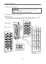
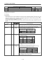
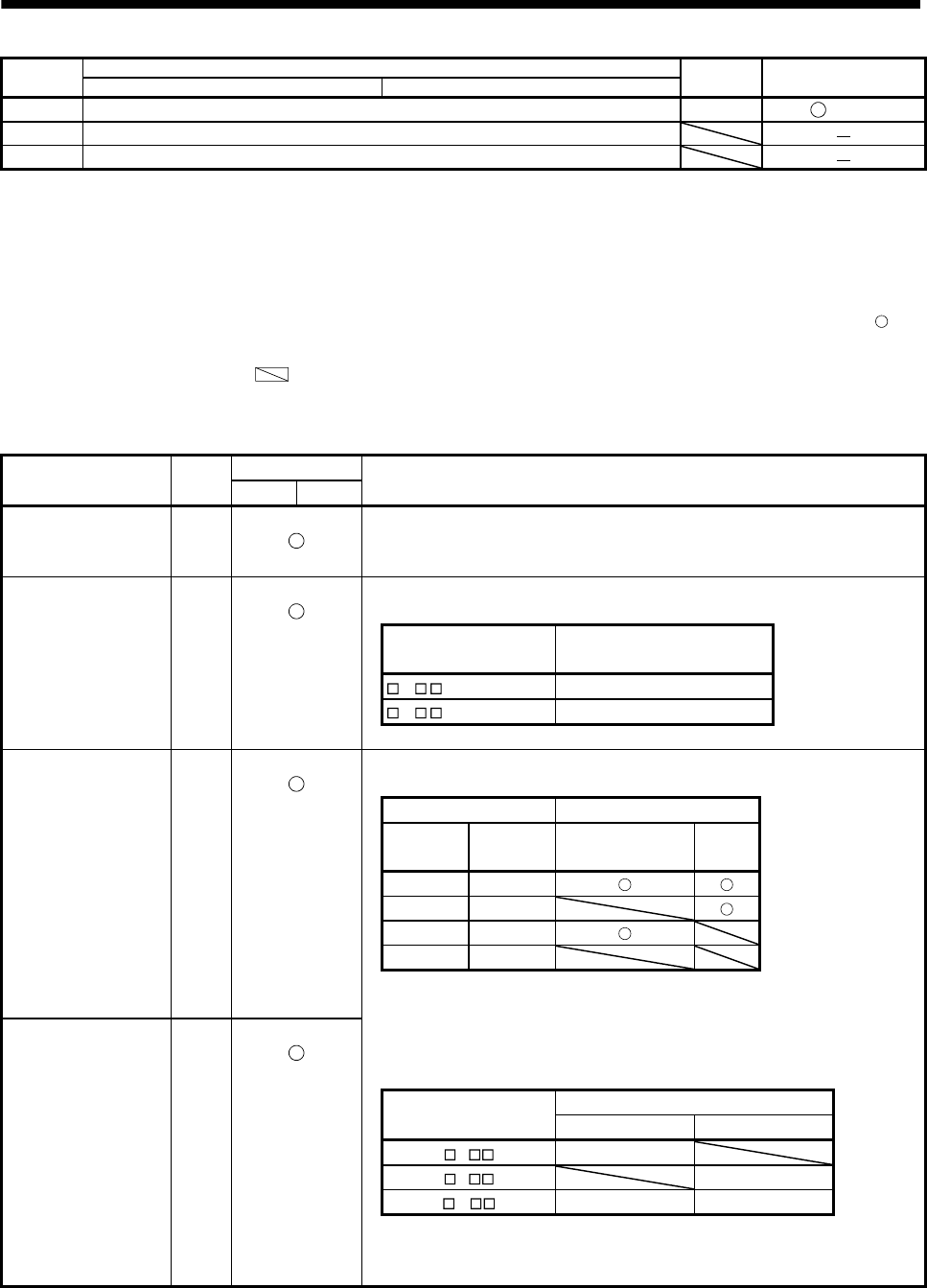
Pin No.
Device assigned in the initial status (Symbol)
I/O division Device change
When using the point table When using the BCD input
49 In position (INP) DO-1 (Po09)
50 Shield (SD)
Plate Shield (SD)
3.5 Signal (device) explanation
3.5.1 Devices
(1) Input device
The Connector pin No. column indicates the connector pin Nos. assigned at default. The device with
can
change the connector pin Nos. assigned by changing the parameter No. PD06 to PD08 and Po02 to Po07.
The devices indicated with
cannot be used.
PT in the table indicates when using a point table, and BCD indicates when using a 6-digit BCD input with
symbol.
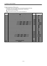
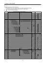
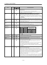
Device Symbol
Connector pin No.
Functions/Applications
PT BCD
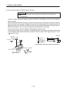
Forced stop EMG CN6-1
Turn EMG off (open between commons) to bring the motor to a forced stop state,
in which the base circuit is shut off and the dynamic brake is operated. Turn EMG
on (short between commons) in the forced stop state to reset that state.
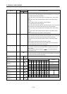
Proximity dog DOG CN6-2
When DOG is turned OFF, the proximity dog is detected. The polarity of dog
detection can be changed using parameter No. PD16.
Parameter No, PD16 Proximity dog (DOG)
detection polarity
0 (initial value) OFF
1 ON
Forward rotation stroke
end
LSP CN6-3
To start operation, turn LSP/LSN on. Turn it off to bring the motor to a sudden
stop and make it servo-locked.
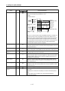
(Note) Input signals Operation
LSP LSN
CCW
direction
CW
direction
1 1
0 1
1 0
0 0
Note. 0: OFF
1: ON
Reverse rotation stroke
end
LSN CN6-4
The stop method can be changed by parameter No. PD20.
Set parameter No. PD01 as indicated below to switch on the signals (keep
terminals connected) automatically in the servo amplifier.
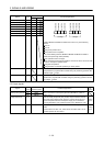
Parameter No, PD01
Status
LSP LSN
4 Automatic ON
8 Automatic ON
C Automatic ON Automatic ON
When LPS or LSN turns OFF, an external stroke limit warning (A99) occurs, and
Warning (WNG) turns OFF. However, when using WNG, set the parameter No.
PD06 to PD08/Po02 to Po07 to make it usable.