4 - 20
4. OPERATION
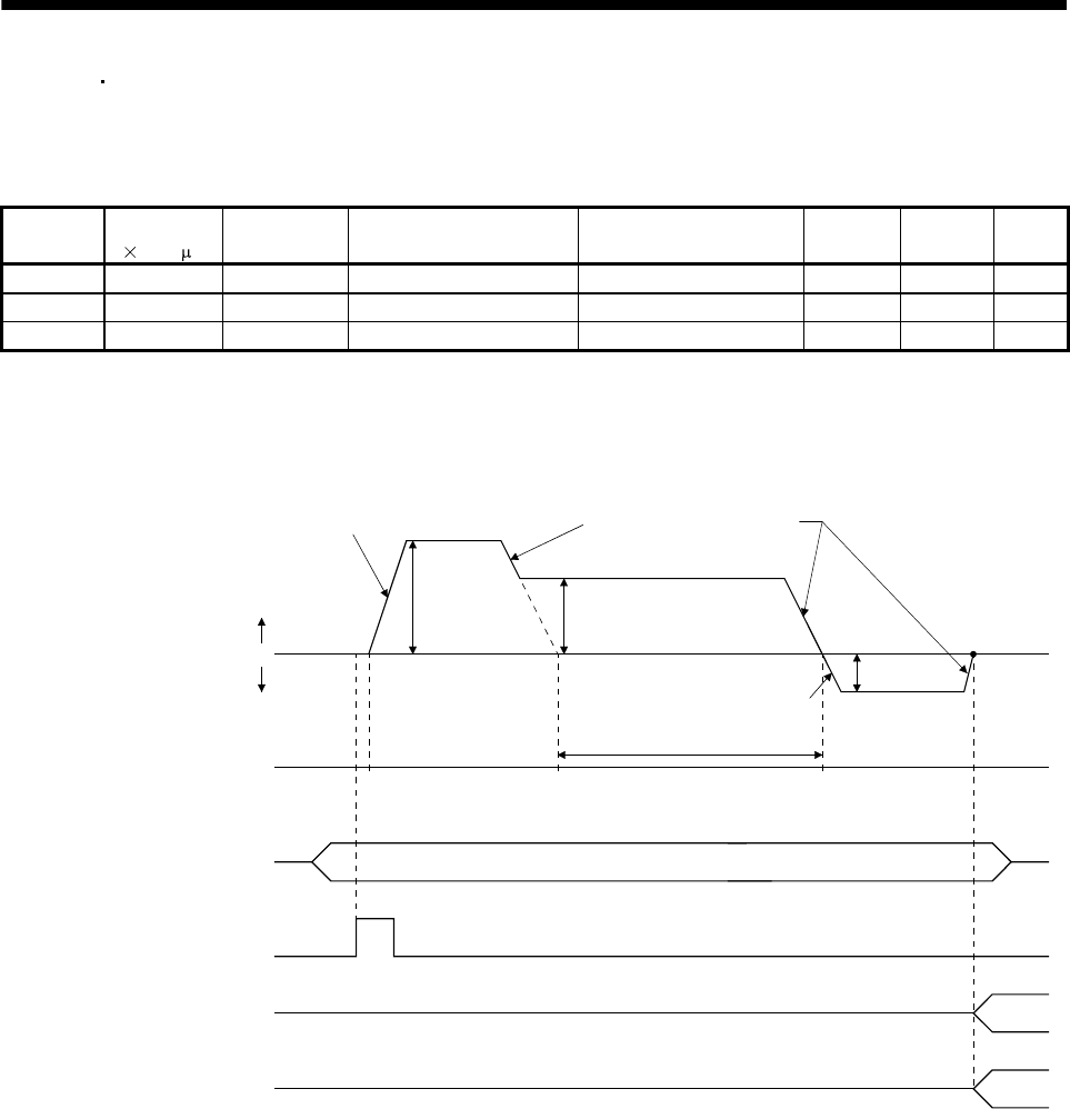
Positioning that reverses the direction midway
The operation example given below assumes that the set values are as indicated in the following
table. Here, the point table No. 1 uses the absolute value command system, the point table No. 2
the incremental value command system, and the point table No. 3 the absolute value system.
Point table
No.
Position data
[
10
STM
m]
Servo motor
speed [r/min]
Acceleration time constant
[ms]
Deceleration time constant
[ms]
Dwell [ms]
(Note 1)
Auxiliary
function
M code
1 5.00 3000 100 150 0 1 05
2 7.00 2000 Invalid Invalid 0 1 10
3 8.00 1000 Invalid Invalid 0 0 (Note 2) 15
Note 1. Always set "0".
2. Always set "0" or "2" to the auxiliary function of the last point table among the consecutive point tables.
0: When point table is used in absolute value command system
1: When point table is used in incremental value command system
Deceleration time constant
of point table No. 1 (150)
Servo motor speed
Forward rotation start
(ST1)
ON
OFF
05.00 12.00
Speed
(2000)
1
0r/min
Acceleration time constant
of point table No. 1 (100)
Speed
(1000)
7.00
Acceleration time constant of
point table No. 1 (100)
1
Point table No. out put
(PT0 to PT7)
05
M code
8.00
Forward
rotation
Reverse
rotation
Position address
Selected point table No.
Speed
(3000)


