


5 - 24
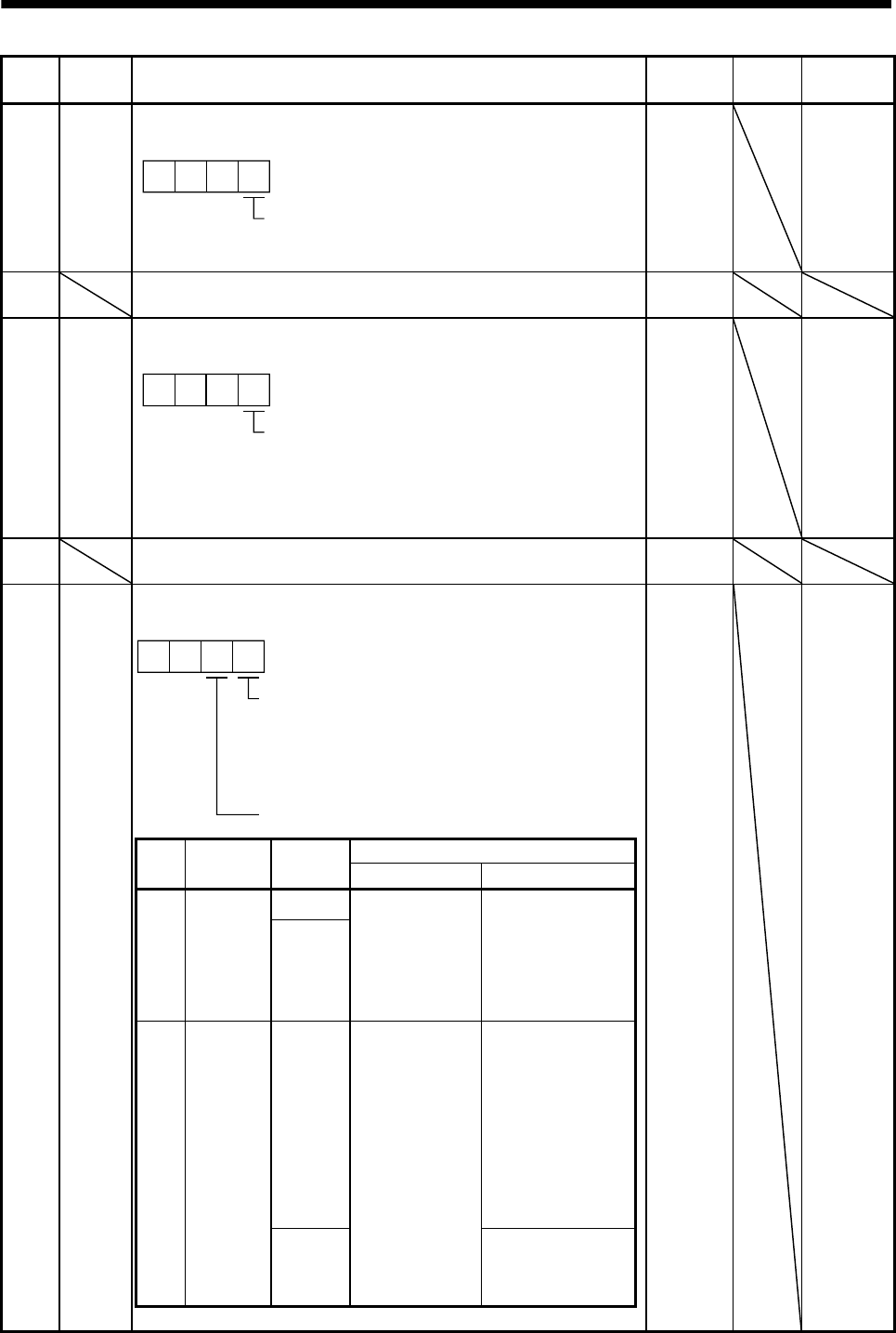
5. PARAMETERS
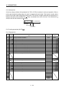
No. Symbol Name and function
Initial
value
Unit
Setting
range
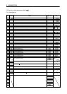
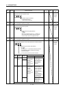
PC24 *COP3 Function selection C-3
Select the unit of the in-position range.
In-position range unit selection
0: Command input unit
1: Servo motor encoder unit
000
0000h Refer to
name and
function
column.
PC25 For manufacturer setting
Do not change this value by any means.
0000h
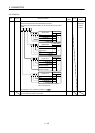
PC26 *COP5 Function selection C-5
Select the stroke limit warning (A99).
Stroke limit warning (A99) selection
0: Valid
1: Invalid
When this parameter is set to "1", A99 will not
occur if the forward rotation stroke end (LSP) o
r
reverse rotation stroke end (LSN) turns OFF.
000
0000h Refer to
name and
function
column.
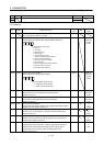
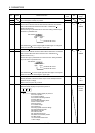
PC27 For manufacturer setting
Do not change this value by any means.
0000h
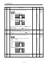
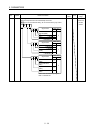
PC28 *COP7 Function selection C-7
Select the display method of the current position and command position.
Current position/command position selection
00
Electronic gear fraction clear selection
0: Invalid
1: Valid
By setting it to “1”, the fraction of the last command
by the electronic gear is cleared when starting
automatic operation.
0000h Refer to
name and
function
column.
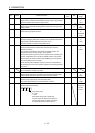
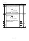
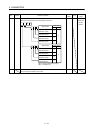
Set
value
Display
method
Operation
mode
Status display description
Current position Command position
0 Positioning
display
Automatic The actual
current position
where the
machine home
position is
assumed as 0 is
displayed.
The command
current position
where the machine
home position is
assumed as 0 is
displayed.
Manual
1 Roll feed
display
Automatic The actual
current position
where the
automatic
operation start
position is
assumed as 0 is
displayed.
The count starts from
0 when the start
signal is turned ON,
and the command
current position to
the target position is
displayed.
During a stop, the
command position of
the selected point
table is displayed.
Manual The command
position of the
selected point table
is displayed.