13 - 89
13. OPTIONS AN
D AUXILIARY EQUIPMENT
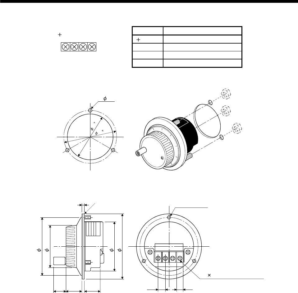
(3) Terminal layout
5 to
0V A B
12V
Signal Description
5 to 12V Power input
0V Common for power and signal
A A-phase pulse output
B B-phase pulse output
(4) Installation
6
2
2
0
7
2
0
.
2
3- 4.8
Equally spaced
Panel cut
(5) Outline drawing
8.89 7.6
M3 6 may only be installed
12V 0V A B
5V to
3-M4 stud L10
P.C.D72 equally spaced
MANUAL
TYPE
SERIALNO.
3.6
Packing t2.0
16 20
27.0
[Unit: mm]
70
50
60
80


