


3 - 6
3. SIGNALS AND WIRING
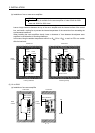
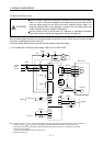
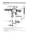
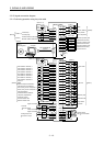
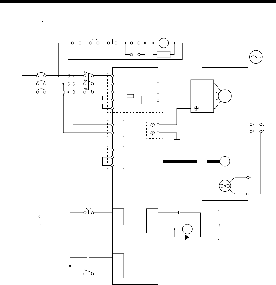
(5) MR-J3-500T
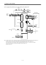
MR-J3-700T
(Note 4)
Forced stop
(Note 4)
Forced
stop
RA
NFB MC
L
1
L2
L3
3-phase
200 to
230VAC
Servo amplifier
C
SK
MC
ON
OFF
MC
P
U
V
W
TE1
PE
L
11
L21
TE2
Servo motor
U
V
W
2
3
4
1
M
Motor
Encoder
CN2
(Note 3)
Encoder cable
(Note 5)
P1
P
2
N
TE3
(Note 1)
(Note 2)
Built-in
regenerative
resistor
EMG
ALM RA
DICOM
DOCOM
24VDC
Trouble
DOCOM
CN6 CN6
SON
24VDC
DICOMD
CN10
MR-J3-D01
DOCOMD
Servo-on
Cooling fan
(Note 6)
Power supply
of Cooling fan
BU
BV
NFB
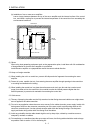
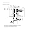
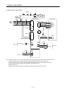
Note 1. Always connect P1 and P2. (Factory-wired.) When using the power factor improving DC reactor, refer to section 13.11.
2. When using the regenerative option, refer to section 13.2.
3. For encoder cable, use of the option cable is recommended. Refer to section 13.1 for selection of the cable.
4. For the sink I/O interface. For the source I/O interface, refer to section 3.8.3.
5. Refer to section 13.10.
6. A cooling fan is attached to the HA-LP601 and the HA-LP701M servo motors. For power supply specification of the cooling fan,
refer to section 3.10.2 (3) (b).