3 - 34
3. SIGNALS AND WIRING
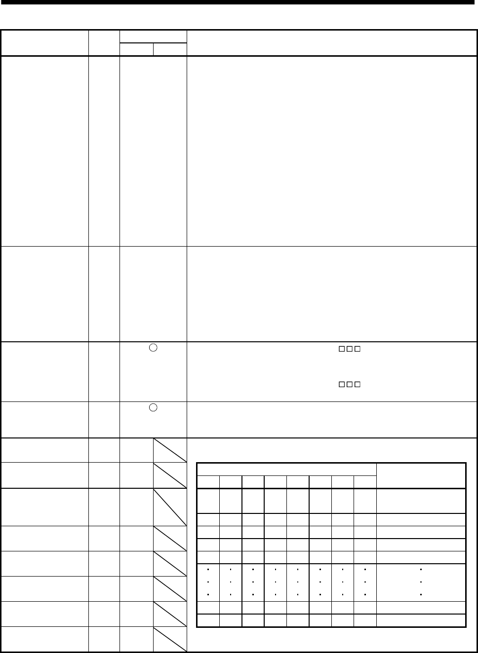
Device Symbol
Connector pin No.
Functions/Applications
PT BCD
Forward rotation start ST1 CN10-35 1. In absolute value command system
Turning ST1 ON for automatic operation executes positioning once on the basis
of the position data set to the point table.
Turning ST1 ON for a home position return immediately starts a home position
return.
Keeping ST1 ON for JOG operation performs rotation in the forward rotation
direction.
Forward rotation indicates the address increasing direction.
2. In incremental value command system
Turning ST1 ON for automatic operation executes positioning once in the forward
rotation direction on the basis of the position data set to the point table.
Turning ST1 ON for a home position return immediately starts a home position
return.
Keeping ST1 ON for JOG operation performs rotation in the forward rotation
direction.
Forward rotation indicates the address increasing direction.
Reverse rotation start ST2 CN10-36 Use this device in the incremental value command system.
Turning ST2 ON for automatic operation executes positioning once in the reverse
rotation direction on the basis of the position data set to the point table.
Keeping ST2 ON for JOG operation performs rotation in the reverse rotation
direction.
Reverse rotation indicates the address decreasing direction.
Reverse rotation start (ST2) is also used as the start signal of the high-speed
automatic positioning function to the home position.
Clear CR When the parameter No. PD22 setting is " 1 ", the position control counter
droop pulses is cleared at the leading edge of CR. The pulse width should be
10ms or more.
When the parameter No. PD22 setting is "
2 ", the pulses are always
cleared while CR is on.
Gain changing CDP When CDP is turned ON, the load inertia moment ratio and the corresponding
gain values change to the values of parameter No. PB29 to PB32. To change the
gain using CDP, make the auto tuning invalid.
Point table No.
selection 1
DI0 CN10-1 The point table No. and the home position return are selected by DI0 to DI7.
Point table No. DI1 CN10-2 (Note) Device
Selection
selection 2 DI7 DI6 DI5 DI4 DI3 DI2 DI1 DI0
Point table No.
selection 3
DI2 CN10-3
0 0 0 0 0 0 0 0
Home position
return mode
0 0 0 0 0 0 0 1 Point table No.1
Point table No. DI3 CN10-4 0 0 0 0 0 0 1 0 Point table No.2
selection 4 0 0 0 0 0 0 1 1 Point table No.3
Point table No. DI4 CN10-5 0 0 0 0 0 1 0 0 Point table No.4
selection 5
Point table No. DI5 CN10-6
selection 6
Point table No. DI6 CN10-7 1 1 1 1 1 1 1 0 Point table No.254
selection 7 1 1 1 1 1 1 1 1 Point table No.255
Point table No.
selection 8
DI7 CN10-8 Note. 0: OFF
1: ON


