


13 - 49
13. OPTIONS AN
D AUXILIARY EQUIPMENT
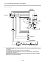
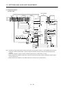
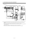
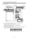
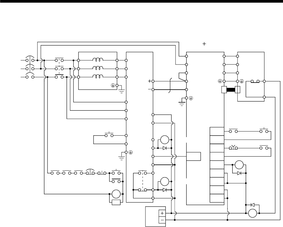
(3) Connection diagram
(a) 200V class
Thermal
relay
(Note 2)
24VDC
power
supply
(Note 1)
(Note 3)
(Note 4)
Servo amplifier
Servo motor
(Note 1)
(Note 5)
(Note 1)
(Note 1) (Note 2)
C
B
R/L11
3-phase
200 to
230VAC
S/L21
T/L
31
R2/L1
S2/L22
R2/L12
T2/L
32
S2/L
2
SD
RDYB
RDYA
RSO
SE
A
T2/L
3
R/L
11
S/L
21
T/MC1
RES
SD
L
11
L
21
RES
U
V
W
RA2
RA1
CN2
MC
NFB
FR-CVL FR-CV
MC
RA2 RA3 RA4
EMG
OFF
ON
RESET
SK
MC
MR-J3-D01
RA3
RA4
U
V
W
OHS2
OHS1
RA2
RA1
EMG
SON
P
N
P
1
P/L
N/L
EMG
SON
DOCOM
DICOMD
DICOM
DOCOMD
ALM
DOCOMD
DOCOM
P
24
(Note 3)
(Note 1)
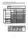
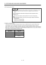
Note 1. Configure a sequence that will shut off main circuit power at an forced stop or at FR-CV or servo amplifier alarm occurrence.
2. For the servo motor with thermal relay, configure a sequence that will shut off main circuit power when the thermal relay
operates.
3. For the servo amplifier, configure a sequence that will switch the servo on after the FR-CV is ready.
4. When using the servo amplifier of 7kW or less, make sure to disconnect the wiring of built-in regeneration resistor (3.5kW or
less: P-D, 5k/7kW: P-C).
5. When using the servo amplifier of 11k to 22kW, make sure to connect P
1
and P. (Factory-wired.)