1 - 26
1. FUNCTIONS AND CONFIGURATION
(1) For MR-J3-350T or less
MR-J3-200T4 or less
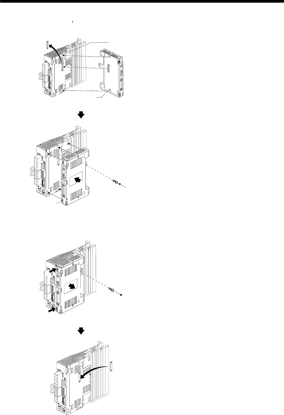
(a) Installation of the MR-J3-D01
2)
2)
1)
Guide hole
Guide
p
ins
1) Remove the cover of connector for connecting
an option. Make sure to storage the removed
cover.
2) Insert the guide pins through the each guide
hole on the side of servo amplifier.
Knobs
3)
4)
3) Push the MR-J3-D01 until the knobs click.
4) Tighten the MR-J3-D01 with the enclosed
installing screw(M4).
(b) Removal of the MR-J3-D01
1)
2)
b)
a)
1) Loosen the installing screw.
2) Keep pushing the knobs( a) , b) ) and pull out
the MR-J3-D01 to the arrow direction. Avoid
pulling out the MR-J3-D01 under it is
tightened.
When removing the MR-J3-D01, make sure to
reinstall the cover of connector for connecting an
option to avoid dust and dirt.


