1 - 27
1. FUNCTIONS AND CONFIGURATION
(2) For MR-J3-350T4
MR-J3-500T(4) MR-J3-700T(4)
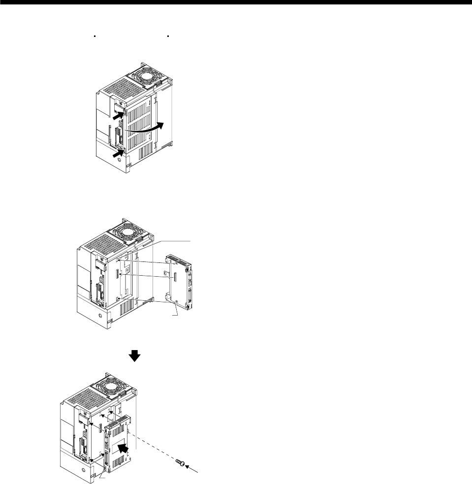
(a) Removal of the side cover
1)
a)
b)
Keep pushing the knobs( a) , b) ) and pull out the
side cover to the arrow direction.
(b) Installation of MR-J3-D01
1)
1)
Guide pins
Guide hole
1) Insert the guide pins through the each guide
hole on the side of servo amplifier.
Knobs
2)
3)
2) Push the MR-J3-D01 until the knobs click.
3) Tighten the MR-J3-D01 with the enclosed
installing screw(M4).


