4 - 29
4. OPERATION
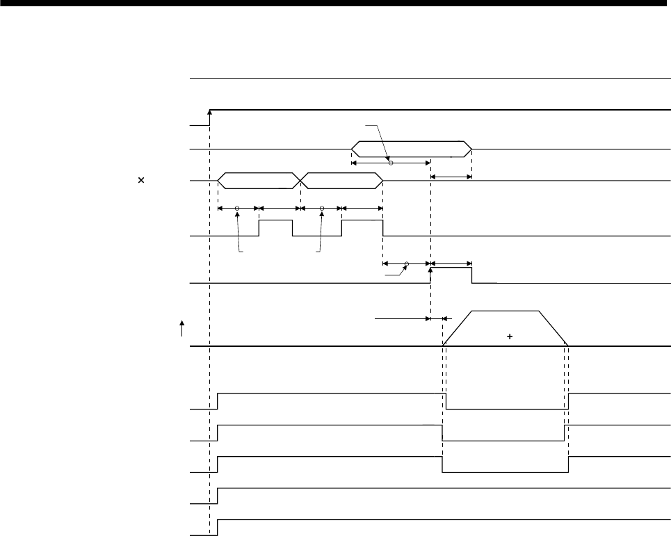
(3) Timing chart
ON
OFF
ON
OFF
ON
OFF
ON
OFF
ON
OFF
ON
OFF
ON
ON
Strobe(STRB)
Position 1) last 3 digits
Position 1) first 3 digits
OFF
ON
OFF
Forward rotation start (ST1)
(Note 1)
OFF
Speed 1)
Position 1) Speed 1)
5ms
or more
5ms or more
(Note 2)
4ms or more
(Note 2)
3ms or more
(Note 2)
5ms
or more
5ms
or more
5ms
or more
3ms or less
Automatic/manual selection
(MD0)
Servo-on (SON)
Speed selection 1 to 4
Digital switch BCD (3 digits 2)
Servo motor speed
Forward
rotation
In position (INP)
Rough match (CPO)
Movement finish (MEND)
Ready (RD)
Trouble (ALM)
0r/min
Note 1. In the incremental system, the reverse rotation start (ST2) can also be used. In this case, the same timing chart as ST1 can be
applied.
2. External input signal detection delays by the input filter setting time of parameter No. PD19. Also, make up a sequence that will
change the position data earlier by the time that takes into account the output signal sequence from the controller and the
variation of a signal change due to the hardware.


