


13 - 24
13. OPTIONS AN
D AUXILIARY EQUIPMENT
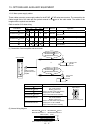
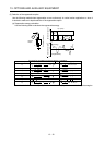
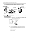
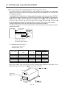
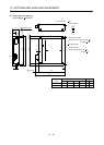
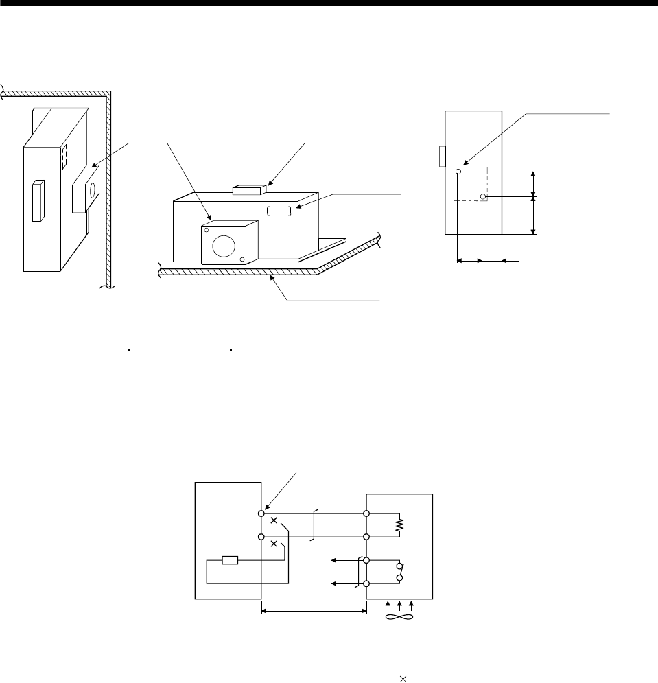
For the MR-RB50, MR-RB3M-4, MR-RB3G-4 or MR-RB5G-4 install the cooling fan as shown.
4082.5
82.5
133
Cooling fan installation screw hole dimensions
2-M3 screw hole
(for cooling fan installation)
Depth 10 or less
(Screw hole already
machined)
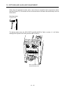
Cooling fan Terminal block
Thermal relay
Installation surface
Horizontal installation
Vertical
installation
Top
Bottom
[Unit : mm]
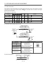
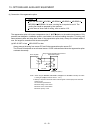
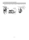
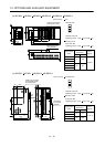
(b) MR-J3-350T4
MR-J3-500T(4) MR-J3-700T(4)
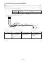
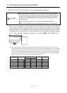
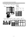
Always remove the wiring (across P-C) of the servo amplifier built-in regenerative resistor and fit the
regenerative option across P-C.
The G3 and G4 terminals act as a thermal sensor. G3-G4 is opened when the regenerative option
overheats abnormally.
Servo amplifier
Regenerative option
Always remove wiring (across P-C) of servo
amplifier built-in regenerative resistor.
P
C
G4
G3
(Note 2)
5m or less
Cooling fan (Note 1)
C
P
Note 1. When using the MR-RB51, MR-RB3G-4, MR-RB5G-4, MR-RB-34-4 or MR-RB54-4,
forcibly cool it with a cooling fan (92
92, minimum air flow : 1.0m
3
).
2. Make up a sequence which will switch off the magnetic contactor (MC) when abnormal
heating occurs.
G3-G4 contact specifications
Maximum voltage: 120V AC/DC
Maximum current: 0.5A/4.8VDC
Maximum capacity: 2.4VA