


7 - 6
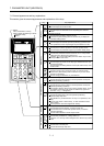
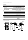
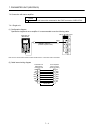
7. PARAMETER UNIT (MR-PRU03)
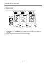
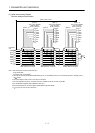
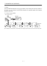
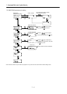
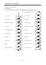
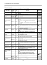
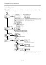
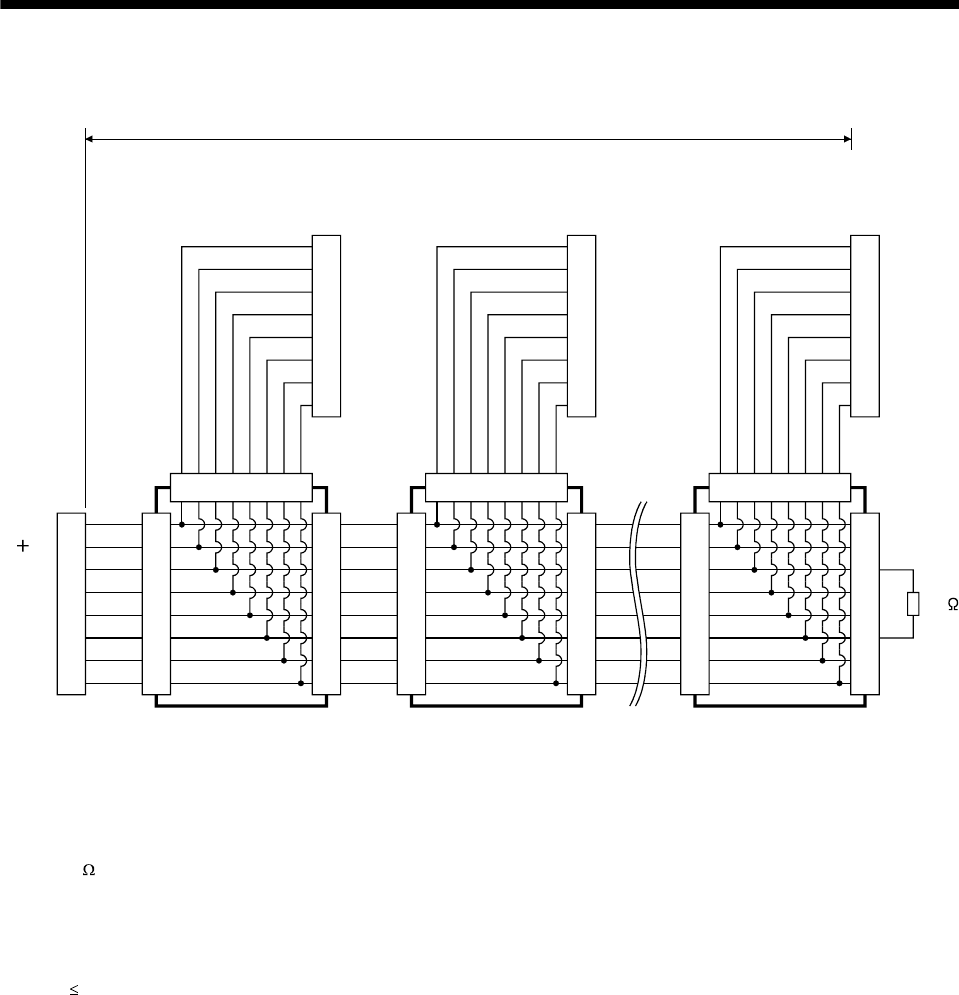
(2) Cable internal wiring diagram
Wire the cables as shown below.
Parameter
unit
7
1
2
3
4
5
6
8
7
1
2
3
4
5
6
8
12345678
7
1
2
3
4
5
6
8
(Note 4, 5)
LG
P5D
RDP
SDN
SDP
RDN
LG
NC
(Note 5)
(Note 1)
Axis 1 servo amplifier
CN3 connector
(RJ45 connector)
7
1
2
3
4
5
6
8
7
1
2
3
4
5
6
8
12345678
7
1
2
3
4
5
6
8
LG
P5D
RDP
SDN
SDP
RDN
LG
NC
(Note 4)
(Note 5)
(Note 1)
Axis 2 servo amplifier
CN3 connector
(RJ45 connector)
7
1
2
3
4
5
6
8
7
1
2
3
4
5
6
8
12345678
7
1
2
3
4
5
6
8
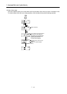
LG
P5D
RDP
SDN
SDP
RDN
LG
NC
(Note 4)
150
RDP
RDN
(Note 2)
(Note 1, 7)
Axis n servo amplifier
CN3 connector
(RJ45 connector)
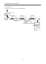
(Note 3) 30m or less
GND
RDP
SDN
SDP
RDN
GND
5V
NC
(Note 5)
7
1
2
3
4
5
6
8
(Note 6) Branch connector (Note 6) Branch connector (Note 6) Branch connector
Note 1. Recommended connector (Hirose Electric)
Plug: TM10P-88P
Connection tool: CL250-0228-1
2. The final axis must be terminated between RDP (pin No. 3) and RDN (pin No.6) on the receiving side (servo amplifier) with a
150
resistor.
3. The overall length is 30m or less in low-noise environment.
4. The wiring between the branch connector and servo amplifier should be as short as possible.
5. Use the EIA568-compliant cable (10BASE-T cable, etc.).
6. Recommended branch connector: BMJ-8 (Hakko Electric Machine Works)
7. n
32 (Up to 32 axes can be connected.)