


1 - 9
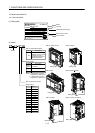
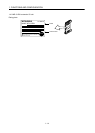
1. FUNCTIONS AND CONFIGURATION
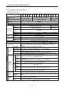
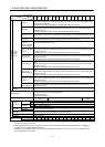
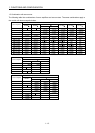
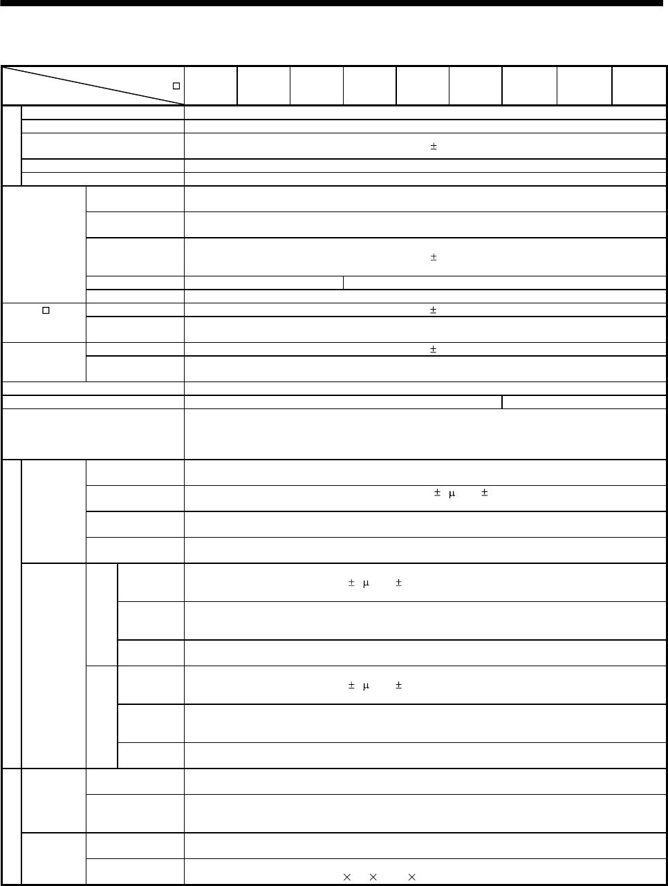
(2) 400V class
Servo amplifier
MR-J3-
Item
60T4 100T4 200T4 350T4 500T4 700T4 11KT4 15KT4 22KT4
Power supply
Voltage/frequency 3-phase 380 to 480VAC, 50/60Hz
Permissible voltage fluctuation 3-phase 323 to 528VAC
Permissible frequency
fluctuation
Within
5%
Power supply capacity Refer to section 12.2
Inrush current Refer to section 12.5
Control circuit
power supply
Voltage,
frequency
1-phase 380 to 480VAC, 50/60Hz
Permissible
voltage fluctuation
1-phase 323 to 528VAC
Permissible
frequency
fluctuation
Within
5%
Input 30W 45W
Inrush current Refer to section 12.5
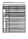
MR-J3- T
Interface power
supply
Voltage 24VDC
10%
Power supply
capacity
(Note 1) 150mA or more
MR-J3-D01
Interface power
supply
Voltage 24VDC
10%
Power supply
capacity
(Note 2) 800mA or more
Control System Sine-wave PWM control, current control system
Dynamic brake Built-in External option
Protective functions
Overcurrent shut-off, regenerative overvoltage shut-off, overload shut-off (electronic thermal relay),
servo motor overheat protection, encoder error protection, regenerative brake error protection,
undervoltage, instantaneous power failure protection, overspeed protection, excessive error
protection
Command system
Point table
number
input
Operational
specifications
Positioning by specifying the point table No. (255 points)
Position command
input
Set in point table. 1-point feed length setting range: 1[ m] to 999.999[mm]
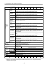
Speed command
input
Acceleration/deceleration time is set in point table.
S-pattern acceleration/deceleration time constant is set in parameter No. PC13.
System
Signed absolute value command system, incremental value command system, signed absolute
value command/incremental value command specifying system
Position
command
data input
BCD input
Position
command
input
Digital switch or contact input of 6-digit BCD with symbol
1-point feed length setting range:
1[ m] to 999.999[mm].
Speed
command
input
The motor speed and acceleration/deceleration time of the point table No.1 to 15 is selected by
contact input.
S-pattern acceleration/deceleration time constant is set in parameter No.PC13.
System
Signed absolute value command system, incremental value command system, signed absolute
value command/incremental value command specifying system
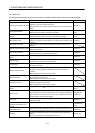
RS-422
communication
Position
command
input
Positioning command data setting by RS-422 communication
1-point feed length setting range:
1[ m] to 999.999[mm].
Speed
command
input
The motor speed and acceleration/deceleration time is set via RS-422 communication.
S-pattern acceleration/deceleration time constant is set in parameter No. PC13.
System
Signed absolute value command system, incremental value command system, signed absolute
value command/incremental value command specifying system
Operation mode
Automatic
operation
mode
Point table
Point table number input, position data input system
Positioning operation is performed once in accordance with the position and speed commands.
Automatic
continuous
operation
Varied speed operation (2 to 255 speeds), automatic continuous positioning operation (2 to 255
points)
Manual
operation
mode
Jog
Jog operation is performed in accordance with the parameter-set speed command by contact input
or through RS-422 communication function.
Manual pulse
generator
Manual feed is made by manual pulse generator.
Command pulse multiplication:
1, 10 or 100 is selected using parameter.