4 - 10
4. OPERATION
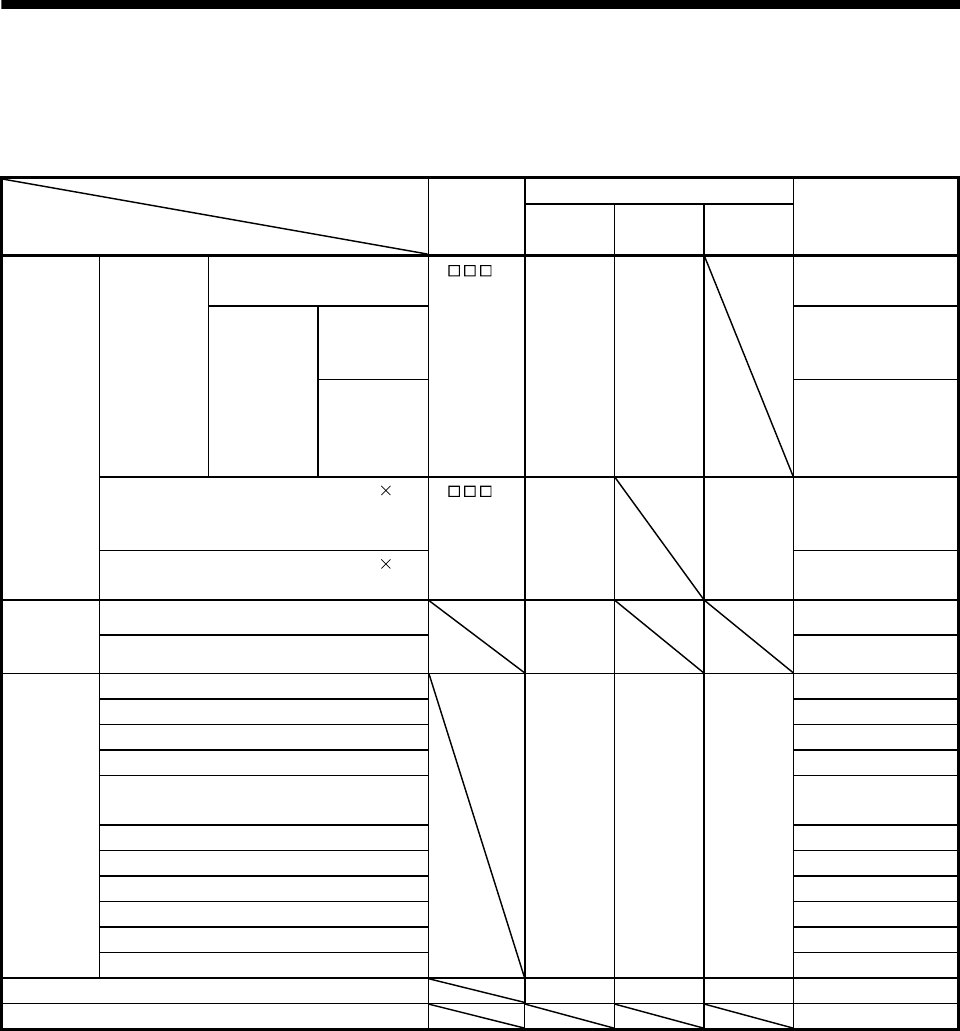
4.4 Operation mode and selection method
This servo has the operation modes indicated in the following table. Select an operation mode to be used with
a parameter and input devices. Parameters and input devices filled with a diagonal line are not required to set.
Selection item of operation mode
Operation mode
Parameter
No. Po10
setting
Input device setting (Note)
Refer to
MD0
D10 to
D17
SP0 to
SP3
Automatic
operation
mode
Automatic
operation
with a point
table
One-time positioning
operation
1 ON Option Section 4.5.2 (1)
Automatic
continuous
operation
Speed
changing
operation
Section 4.5.2 (2) (b)
Automatic
continuous
positioning
operation
Section 4.5.2 (2) (c)
Automatic operation by BCD (3 digits 2)
input with the MR-DS60 6-digit digital
switch
2 ON Option Section 4.5.3
Automatic operation by BCD (3 digits 2)
input with the program controller
Section 4.5.4
Manual
operation
mode
JOG operation
OFF Section 4.6.1
Manual pulse generator operation
Section 4.6.2
Home
position
return
mode
Dog type
ON All OFF All OFF Section 4.7.2
Count type Section 4.7.3
Data setting type Section 4.7.4
Stopper type Section 4.7.5
Home position ignorance (Servo-on
position as home position)
Section 4.7.6
Dog type rear end reference Section 4.7.7
Count type front end reference Section 4.7.8
Dog cradle type Section 4.7.9
Dog style right-before Z-phase reference Section 4.7.10
Dog type front end reference Section 4.7.11
Dogless Z-phase reference Section 4.7.12
Automatic positioning function to the home position ON All OFF All OFF Section 4.7.14
Roll feed display function Section 4.8
Note. MD0: Automatic/manual selection, D10 to D17: Point table No. selection 1 to 8, SP0 to SP3: Speed selection 1 to 4


