


3 - 14
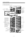
3. SIGNALS AND WIRING
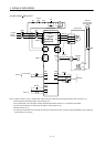
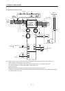
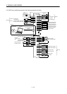
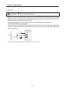
Note 1. To prevent an electric shock, always connect the protective earth (PE) terminal (terminal marked ) of the servo amplifier to the
protective earth (PE) of the control box.
2. Connect the diode in the correct direction. If it is connected reversely, the servo amplifier or the MR-J3-D01 will be faulty and will
not output signals, disabling the forced stop (EMG) and other protective circuits.
3. The forced stop switch (normally closed contact) must be installed.
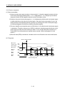
4. Supply 24VDC
10% 150mA current for interfaces of the servo amplifier from the outside. 150mA is the value applicable when
all I/O signals are used. The current capacity can be decreased by reducing the number of I/O points. Refer to section 3.8.2 (1)
that gives the current value necessary for the interface.
5. When starting operation, always turn on forced stop (EMG) and Forward/Reverse rotation stroke end (LSP/LSN). (Normally
closed contacts)
6. Trouble (ALM) turns on in normal alarm-free condition.
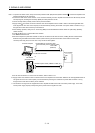
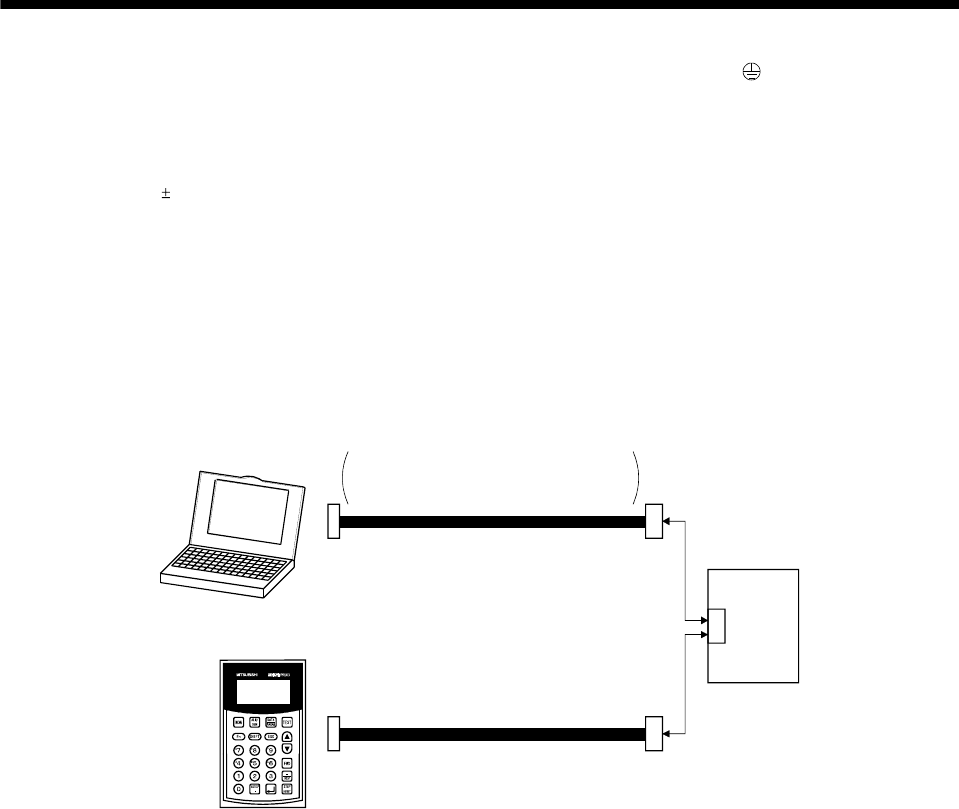
7. Use MRZJW3-SETUP 211E.
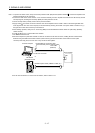
8. Personal computers or parameter modules can also be connected via the CN3 connector, enabling RS-422 communication.
Note that using the USB communication function (CN5 connector) prevents the RS-422 communication function (CN3
connector) from being used, and vice versa. They cannot be used together.
MR-PRU03
parameter module
CN3
EIA568-compliant cable (10BASE-T cable, etc.)
RS-232C/RS-422 conversion cable
Recommended product: Interface cable
DSV-CABV
(Diatrend)
Personal computer
Servo amplifier
or
To RS-232C connector
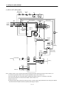
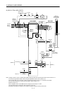
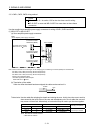
9. For the sink I/O interface. For the source I/O interface, refer to section 3.8.3.
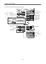
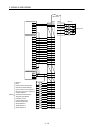
10. Supply 24VDC 10% 800mA current for interfaces of the servo amplifier from the outside. 800mA is the value applicable when all
I/O signals are used. The current capacity can be decreased by reducing the number of I/O points. Refer to section 3.8.2 (1)
that gives the current value necessary for the interface.
11. The 24VDC for I/O signal can be supplied to the servo amplifier and MR-J3-D01 with one 24VDC power supply. In this case,
use the power supply capacity corresponding to the points of the I/O signal to be used.