


3 - 54
3. SIGNALS AND WIRING
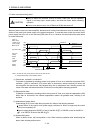
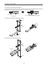
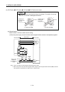
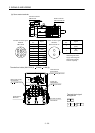
(2) HF-SP series
HC-RP series HC-UP series HC-LP series servo motor
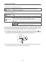
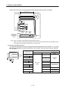
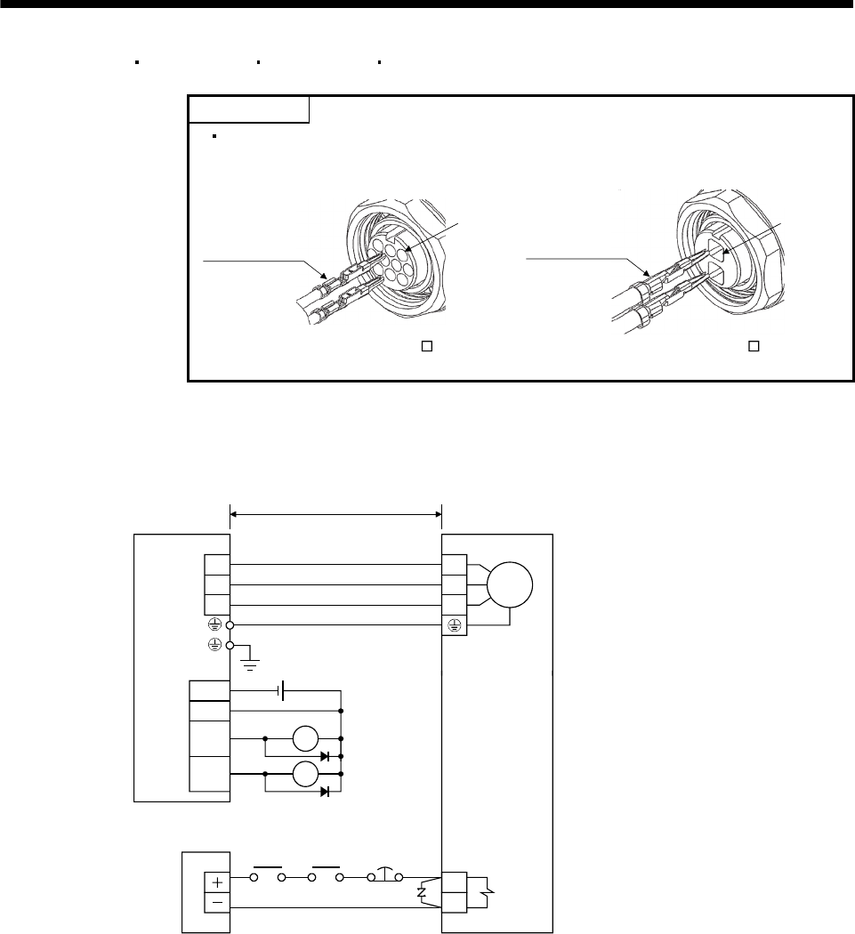
POINT
B Insert a contact in the direction shown in the figure. If inserted in the wrong
direction, the contact is damaged and falls off.
Soldered part
or crimping part
facing up
Soldered part or
crimping part
facing down
Pin No.1Pin No.1
For CM10-SP2S-For CM10-SP10S-
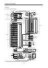
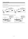
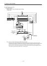
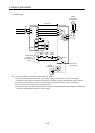
(a) Wiring diagrams
Refer to section 13.9 for the cables used for wiring.
1) When the power supply connector and the electromagnetic brake connector are separately supplied
Servo motor
(Note 1)
Servo amplifier
M
U
V
W
B1
B2
U
V
W
24VDC power
supply for
electromagnetic
brake
50m or less
Forced
stop
(EMG)
Trouble
(ALM)
RA1
24VDC
ALM
DOCOM
DICOM
MBR
CN6
RA1
RA2
Electromagnetic
brake interlock
(MBR)
RA2
(Note 2)
Note 1. There is no polarity in electromagnetic brake terminals B1 and B2.
2. When using a servo motor with electromagnetic brake, assign the electromagnetic brake interlock (MBR) to external
output signal in the parameters No. PD09 to PD11, Po08 and Po09.