


12 - 3
12 CHARACTERISTICS
12.2 Power supply equipment capacity and generated loss
(1) Amount of heat generated by the servo amplifier
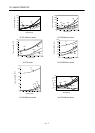
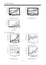
Table 12.1 indicates servo amplifiers' power supply capacities and losses generated under rated load. For
thermal design of an enclosure, use the values in Table 12.1 in consideration for the worst operating
conditions. The actual amount of generated heat will be intermediate between values at rated torque and
servo off according to the duty used during operation. When the servo motor is run at less than the
maximum speed, the power supply capacity will be smaller than the value in the table, but the servo
amplifier's generated heat will not change.
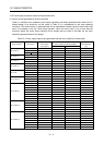
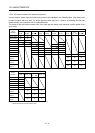
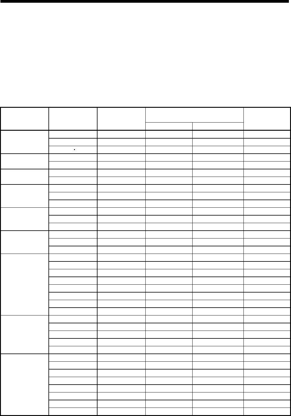
Table 12.1 Power supply capacity and generated heat per servo amplifier at rated output
Servo amplifier Servo motor
(Note 1)
Power supply
capacity[kVA]
(Note 2)
Servo amplifier-generated heat[W]
Area required for
heat dissipation
At rated torque With servo off [m
2
]
MR-J3-10T (1)
HF-MP053 0.3 25 15 0.5
HF-MP13 0.3 25 15 0.5
HF-KP053 13 0.3 25 15 0.5
MR-J3-20T (1)
HF-MP23 0.5 25 15 0.5
HF-KP23 0.5 25 15 0.5
MR-J3-40T (1)
HF-MP43 0.9 35 15 0.7
HF-KP43 0.9 35 15 0.7
MR-J3-60T (4)
HF-SP52 (4) 1.0 40 15 0.8
HF-SP51 1.0 40 15 0.8
HC-LP52 1.0 40 15 0.8
MR-J3-70T
HF-MP73 1.3 50 15 1.0
HF-KP73 1.3 50 15 1.0
HC-UP72 1.3 50 15 1.0
MR-J3-100T (4)
HF-SP102 (4) 1.7 50 15 1.0
HF-SP81 1.5 50 15 1.0
HC-LP102 1.7 50 15 1.0
MR-J3-200T (4)
HF-SP152 (4) 2.5 90 20 1.8
HF-SP202 (4) 3.5 90 20 1.8
HF-SP121 2.1 90 20 1.8
HF-SP201 3.5 90 20 1.8
HC-RP103 1.8 50 15 1.0
HC-RP153 2.5 90 20 1.8
HC-UP152 2.5 90 20 1.8
HC-LP152 2.5 90 20 1.8
MR-J3-350T (4)
HF-SP352 (4) 5.5 130 20 (25) (Note 3) 2.7
HC-RP203 3.5 90 20 1.8
HC-UP202 3.5 90 20 1.8
HC-LP202 3.5 90 20 1.8
HF-SP301 4.8 120 20 2.4
MR-J3-500T (4)
HF-SP502 (4) 7.5 195 25 3.9
HC-RP353 5.5 135 25 2.7
HC-RP503 7.5 195 25 3.9
HC-UP352 5.5 195 25 3.9
HC-UP502 7.5 195 25 3.9
HC-LP302 4.5 120 25 2.4
HA-LP502 7.5 195 25 3.9
HF-SP421 6.7 160 25 3.2