


5 - 23
5. PARAMETERS
No. Symbol Name and function
Initial
value
Unit
Setting
range
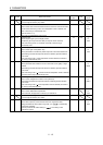
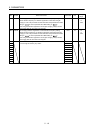
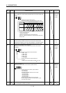
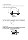
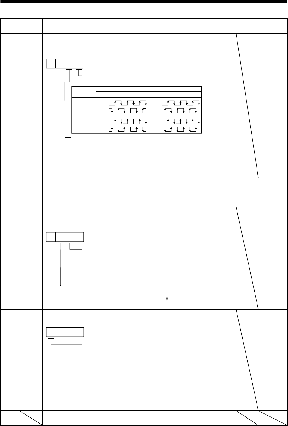
PC19 *ENRS Encoder output pulse selection
Use to select the, encoder output pulse direction and encoder output pulse
setting.
00
Encoder output pulse phase changing
Changes the phases of A, B-phase encoder pulses output .
Encoder output pulse setting selection (refer to parameter No. PA15.)
0: Output pulse designation
1: Division ratio setting
2: Ratio is automatically set to command pulse unit
Setting "2" makes the parameter No. PA15 (encoder output pulse)
setting invalid.
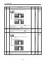
Servo motor rotation direction
Set value
CCW CW
0
1
A-phase
B-phase
A-phase
B-phase
A-phase
B-phase
A-phase
B-phase
0000h Refer to
name and
function
column.
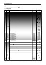
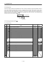
PC20 *SNO Station number setting
Used to specify the station number for RS-422 serial communication.
Always set one station to one axis of servo amplifier. If one station number
is set to two or more stations, normal communication cannot be made.
0 station 0
to
31
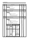
PC21 *SOP RS-422 communication function selection
Select the communication I/F and select the RS-422 communication
conditions.
00
RS-422 communication baud rate selection
0: 9600 [bps]
1: 19200 [bps]
2: 38400 [bps]
3: 57600 [bps]
4: 115200[bps]
RS-422 communication response delay time
0: Invalid
1: Valid, reply sent after delay time of 800 s or more
0000h Refer to
name and
function
column.
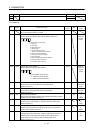
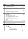
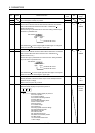
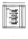
PC22 *COP1 Function selection C-1
Select the encoder cable communication system selection.
00
Encoder cable communication system selection
0: Two-wire type
1: Four-wire type
The following encoder cables are of 4-wire type.
MR-EKCBL30M-L
MR-EKCBL30M-H
MR-EKCBL40M-H
MR-EKCBL50M-H
The other encoder cables are all of 2-wire type.
Incorrect setting will result in an encoder alarm 1 (A16)
or encoder alarm 2 (A20).
0
0000h Refer to
name and
function
column.
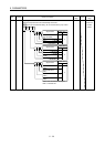
PC23 For manufacturer setting
Do not change this value by any means.
0000h