


14 - 31
14. COMMUNICATION FUNCTION
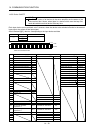
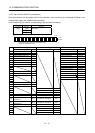
14.5.7 Input devices ON/OFF (test operation)
Each input devices can be turned on/off for test operation. when the device to be switched off exists in the
external input signal, also switch off that input signal.
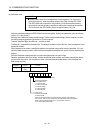
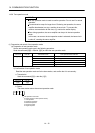
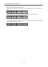
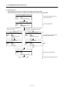
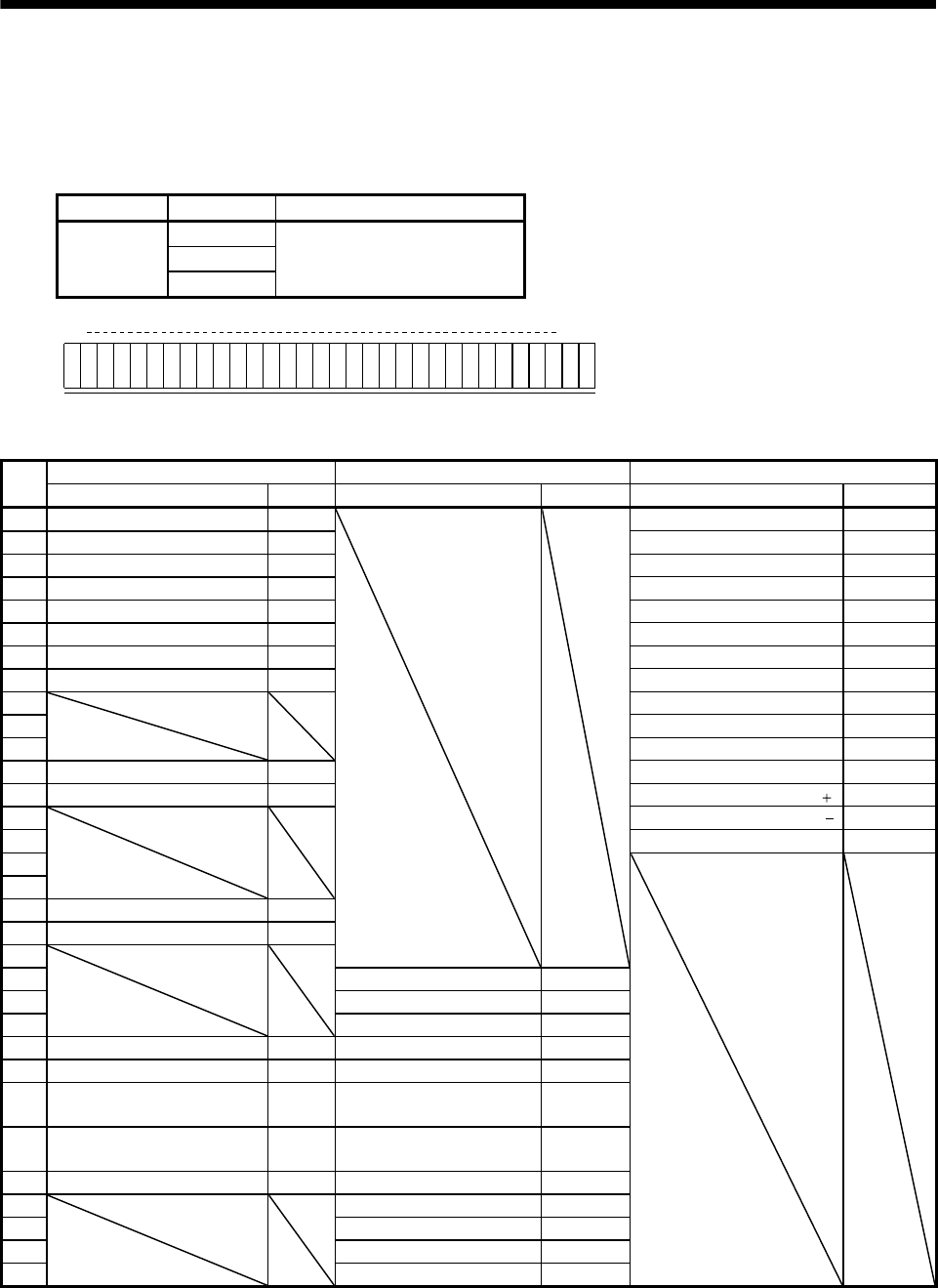
Send command [9] [2], data No. corresponding to the input device and data.
Command Data No. Set data
[9][2] [0][0] See below
[0][1]
[0][2]
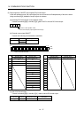
b31 b0
0: OFF
1: ON
b1
Command of each bit is transmitted to the slave
station as hexadecimal data.
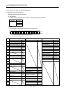
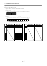
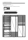
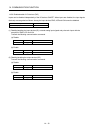
bit Data No. [0][0] Data No. [0][1] Data No. [0][2]
Device name Symbol Device name Symbol Device name Symbol
0 Servo-on SON
Position data input 1 POS00
1 Forward rotation stroke end LSP Position data input 2 POS01
2 Reverse rotation stroke end LSN Position data input 3 POS02
3 External torque limit selection TL Position data input 4 POS03
4 Internal torque limit selection TL1 Position data input 5 POS10
5 Proportion control PC Position data input 6 POS11
6 Reset RES Position data input 7 POS12
7 Clear CR Position data input 8 POS13
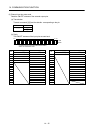
8
Position data input 9 POS20
9 Position data input 10 POS21
10 Position data input 11 POS22
11 Forward rotation start ST1 Position data input 12 POS23
12 Reverse rotation start ST2 Position data input symbol POSP
13
Position data input symbol POSN
14 Strobe input STRB
15
16
17 Automatic/manual selection MD0
18 Proximity dog DOG
19
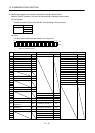
20 Speed selection 1 SP0
21 Speed selection 2 SP1
22 Speed selection 3 SP2
23 Override selection OVR Speed selection 4 SP3
24 Temporary stop/Restart TSTP Point table No. selection 1 DI0
25
Manual pulse generator
multiplication 1
TP0 Point table No. selection 2 DI1
26
Manual pulse generator
multiplication 2
TP1 Point table No. selection 3 DI2
27 Gain switch CDP Point table No. selection 4 DI3
28
Point table No. selection 5 DI4
29 Point table No. selection 6 DI5
30 Point table No. selection 7 DI6
31 Point table No. selection 8 DI7