


13 - 56
13. OPTIONS AN
D AUXILIARY EQUIPMENT
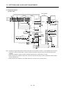
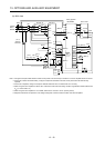
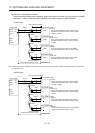
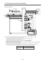
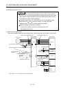
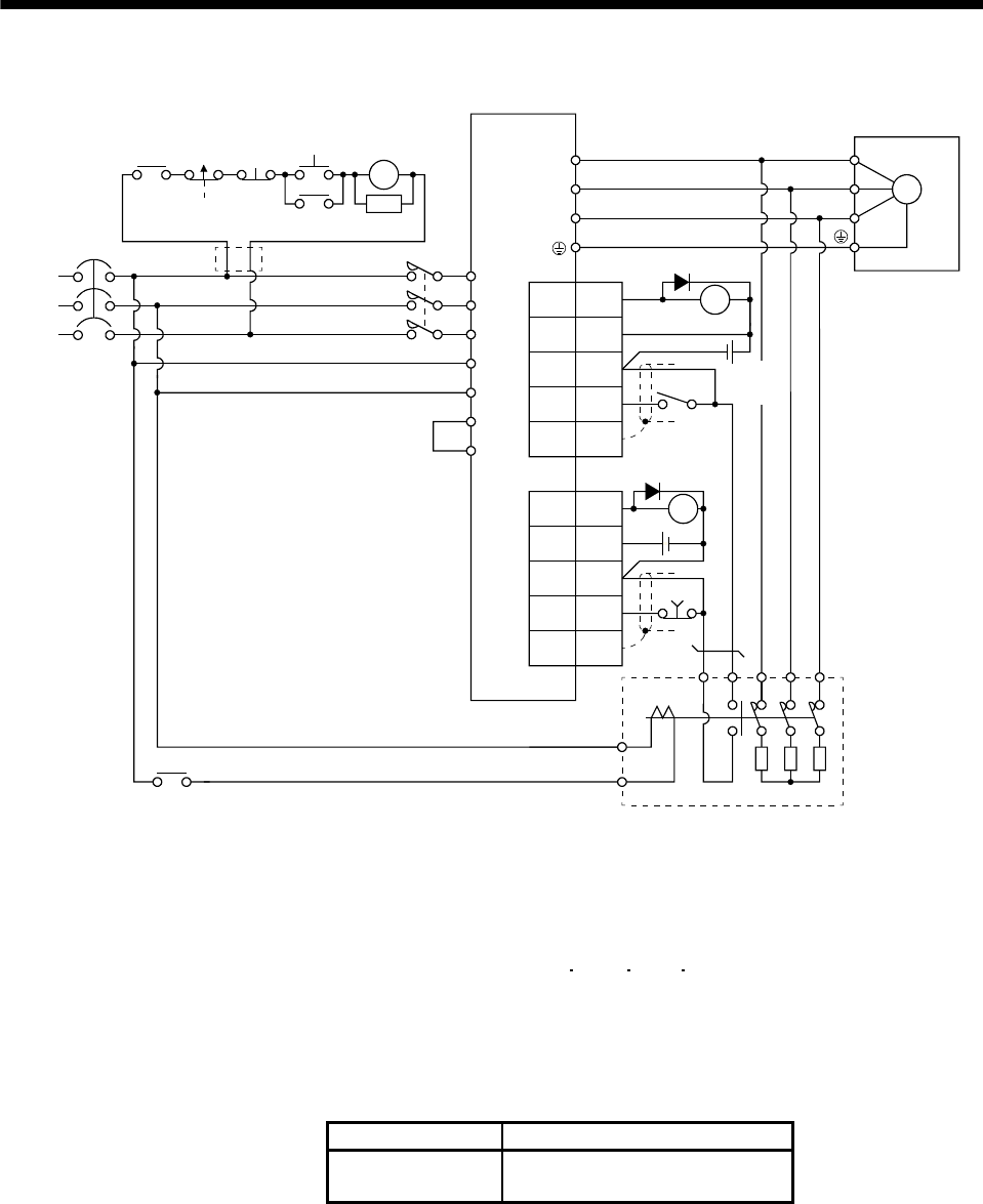
(2) Connection example
Plate SD
NFB
MC
L
11
L21
U
V
W
U
V
W
M
13 U14 V W
External dynamic brake
a
b
Servo amplifier
Servo motor
RA2
MC
SK
MC
ON
OFF
ALM
RA1
Operation-ready
EMG
(Note 1)
L3
L
2
L1
(Note 6)
Power
supply
P
P
1
(Note 2)
(Note 3)
17
21
DB
DOCOMD
SON
RA2
24VDC
(Note 4)
CN10
14
DICOMD
5
17
1
Plate
DICOM
DOCOM
EMG
SD
24VDC
(Note 4)
CN6
15 ALM
RA1
(Note 5)
(Note 7)
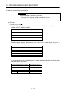
Note 1. Terminals 13, 14 are normally open contact outputs. If the dynamic brake is seized, terminals 13, 14 will open.
Therefore, configure up an external sequence to prevent servo-on.
2. When using the servo amplifier of 11k to 22kW, make sure to connect P
1
and P. (Factory-wired.)
When using the power factor DC reactor, refer to section 13.11.
3. Assign the dynamic brake sequence (DB) in the parameters No.PD09
PD10 Po08 Po09.
4. 24VDC can be supplied from the same power supply.
5. Stepdown transformer is required for coil voltage of magnetic contactor more than 200V class in 400V class servo amplifiers.
6. Refer to section 1.2 for the power supply specification.
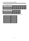
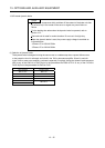
7. The power supply voltage of the inside magnet contactor for 400V class dynamic brake DBU-11K-4 and DBU-22K-4 is
restricted as follows. When using these dynamic brakes, use them within the range of the power supply.
Dynamic brake Power supply voltage
DBU-11K-4
DBU-22K-4
1-phase 380 to 463VAC 50Hz/60Hz