


3 - 35
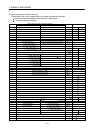
3. SIGNALS AND WIRING
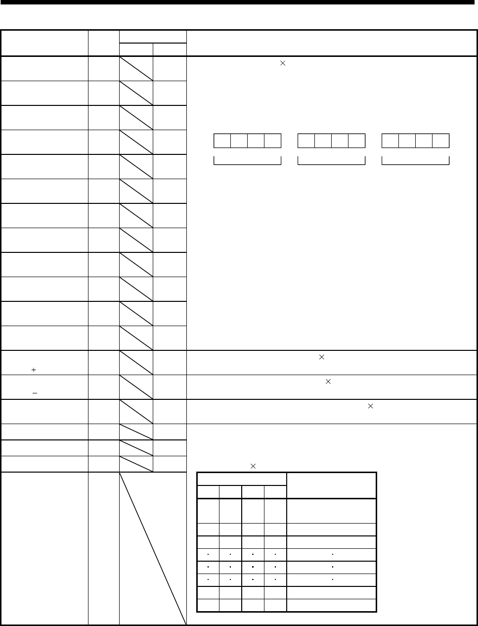
Device Symbol
Connector pin No.
Functions/Applications
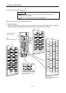
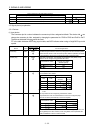
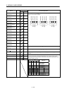
PT BCD
Position data input 1
(1/4digit bit0)
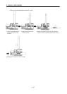
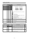
POS00 CN10-1 The 6-digit (BCD 3 digits 2) position data is input by POS00 to POS03, POS10
to POS13 and POS20 to POS23.
3rd digit
6th digit
bit3 POS23
bit2 POS22
bit1 POS21
bit0 POS20
bit3 POS13
bit2 POS12
bit1 POS11
bit0 POS10
bit3 POS03
bit2 POS02
bit1 POS01
bit0 POS00
2nd digit
5th digit
1st digit
4th digit
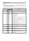
Position data input 2
(1/4digit bit1)
POS01 CN10-2
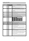
Position data input 3
(1/4digit bit2)
POS02 CN10-3
Position data input 4
(1/4digit bit3)
POS03 CN10-4
Position data input 5
(2/5digit bit0)
POS10 CN10-5
Position data input 6
(2/5digit bit1)
POS11 CN10-6
Position data input 7
(2/5digit bit2)
POS12 CN10-7
Position data input 8
(2/5digit bit3)
POS13 CN10-8
Position data input 9
(3/6digit bit0)
POS20 CN10-9
Position data input 10
(3/6digit bit1)
POS21 CN10-10
Position data input 11
(3/6digit bit2)
POS22 CN10-11
Position data input 12
(3/6digit bit3)
POS23 CN10-12
Position data input
symbol
POSP CN10-15 The plus symbol of the BCD 3 digits
2 is input.
Position data input
symbol
POSN CN10-16 The minus symbol of the BCD 3 digits
2 is input.
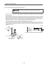
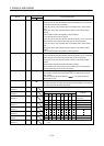
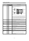
Strobe input STRB CN10-17 A strobe signal used for inputting the BCD 3 digits 2 from the programmable
controller.
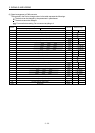
Speed selection 1 SP0 CN10-18 Used to select a point table and the home position return mode with SP0 to SP3.
The motor speed and acceleration/deceleration time constant values of the
selected point table are the speed commands for the positioning operation with
the BCD 3 digits
2 input.
Speed selection 2 SP1 CN10-19
Speed selection 3 SP2
CN10-20
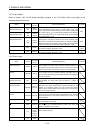
Speed selection 4 SP3 (Note) Device
Selection
SP3 SP2 SP1 SP0
0 0 0 0
Home position
return mode
0 0 0 1 Point table No.1
0 0 1 0 Point table No.2
1 1 1 0 Point table No.14
1 1 1 1 Point table No.15