


5 - 33
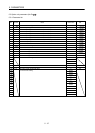
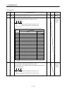
5. PARAMETERS
No. Symbol Name and function
Initial
value
Unit
Setting
range
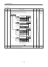
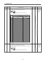
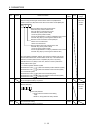
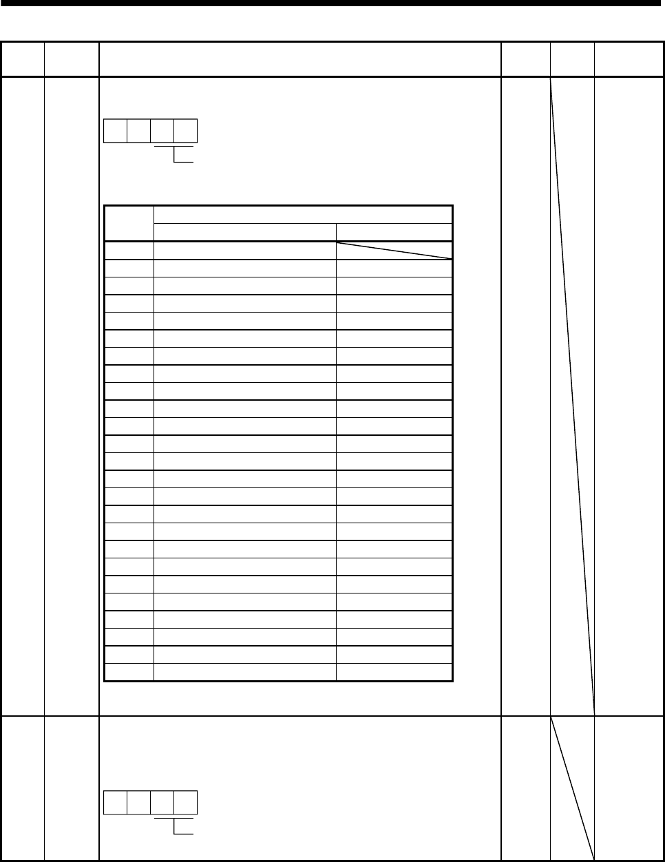
PD09 *DO1 Output signal device selection 1 (CN6-14)
Any output signal can be assigned to the CN6-14 pin.
0
Select the output device of the CN6-14 pin
0
The devices that can be assigned are indicated in the following table.
Setting
(Note)
Output device
Name Symbol
00 Always OFF
02 Ready RD
03 Trouble ALM
04 In position INP
05 Electromagnetic brake interlock MBR
06 Dynamic brake interlock DB
07 Limiting torque TLC
08 Warning WNG
09 Battery warning BWNG
0A Speed command reached SA
0C Zero speed ZSP
0F Variable gain selection CDPS
23 Rough match CPO
24 Home position return completion ZP
25 Position range POT
26 Temporary stop PUS
27 Movement finish MEND
38 Point table No. output 1 PT0
39 Point table No. output 2 PT1
3A Point table No. output 3 PT2
3B Point table No. output 4 PT3
3C Point table No. output 5 PT4
3D Point table No. output 6 PT5
3E Point table No. output 7 PT6
3F Point table No. output 8 PT7
Note. The other setting values than shown in this table are for manufacturer
setting.
0002h Refer to
name and
function
column.
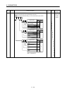
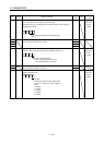
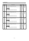
PD10 *DO2 Output signal device selection 2 (CN6-15)
Any output signal can be assigned to the CN6-15 pin.
The devices that can be assigned and the setting method are the same as in
parameter No. PD09.
0
Select the output device of the CN6-15 pin
0
0003h Refer to
name and
function
column.