4 - 23
4. SIGNALS AND WIRING
4.5 Signal (device) explanation
4.5.1 I/O devices
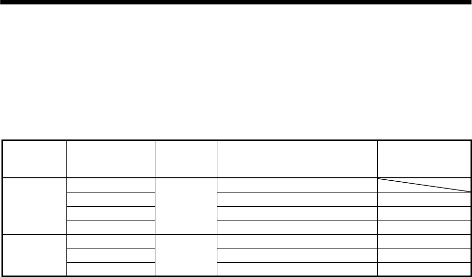
The CN6 connector provides three pins for inputs and three other pins for outputs. Devices assigned to these
pins are changeable. To make this change, configure parameter settings of Nos. PD06 to PD11, PD12, and
PD14. Refer to section 4.8.2 for the I/O interfaces (symbols in the I/O Division field in the table) of the
corresponding connector pins.
Pin type CN6 connector pin No. I/O division Device in initial status
Parameter of change
target device
1 Forced stop (EMG)
2 Proximity dog (DOG) No.PD06
3 Forward rotation stroke end (LSP) No.PD07
Input-only pins
4
DI-1
Reverse rotation stroke end (LSN) No.PD08
14 Ready (RD) No.PD09
15 Trouble (ALM) No.PD10
Output-only pins
16
DO-1
Home position return completion (ZP) No.PD11


