


16 - 3
16. INDEXER POSITIONING OPERATION
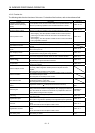
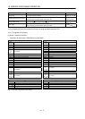
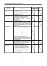
Function Description Reference
Torque limit Servo motor-torque is limited.
Section 16.3.2 (3)
Section 16.11.1 (9)
Output signal (DO) forced output
Output signal can be forced on/off independently of the servo status.
Use this function for output signal wiring check, etc.
Section 7.7.4
Section 8.5.7(4)
Test operation mode
JOG operation
positioning operation DO forced output.
MR Configurator is necessary for this function.
Section 7.7
Section 8.5.7
Limit switch
The servo motor travel region can be limited using the forward rotation
stroke end (LSP)/reverse rotation stroke end (LSN).
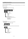
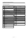
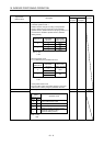
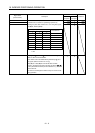
16.2 I/O signals (I/O devices) transferred to/from the programmable controller CPU
16.2.1 I/O signals (I/O devices)
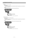
(1) When 1 station is occupied
RYn/RXn: 32 points each, RWrn/RWwn: 4 points each
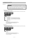
Programmable controller Servo amplifier (RYn) Servo amplifier Programmable controller (RXn)
(Note)
Device No.
Device name
(Note)
Device No.
Device name
RYn0 Servo-on RXn0 Ready
RYn1 Start RXn1 In position
RYn2 Rotation direction specifying RXn2 Rough match
RYn3 RXn3 Home position return completion
to Not available RXn4 Limiting torque
RYn5 RXn5 Not available
RYn6 Operation mode selection 1 RXn6 Electromagnetic brake interlock
RYn7 Operation mode selection 2 RXn7 Temporary stop
RYn8 Monitor output execution demand RXn8 Monitoring
RYn9 Instruction code execution demand RXn9 Instruction code execution completion
RYnA Next station selection 1 RXnA Warning
RYnB Next station selection 2 RXnB Battery warning
RYnC Next station selection 3 RXnC Movement completion
RYnD Next station selection 4 RXnD Dynamic brake interlock
RYnE Next station selection 5 RXnE
RYnF to Not available
to Not available RX(n 1)9
RY(n 1)9 RX(n 1)A Trouble
RY(n 1)A Reset RX(n 1)B Remote station communication ready
RY(n 1)B RX(n 1)C
to Not available to Not available
RY(n 1)F RX(n 1)F
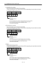
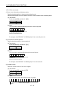
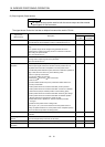
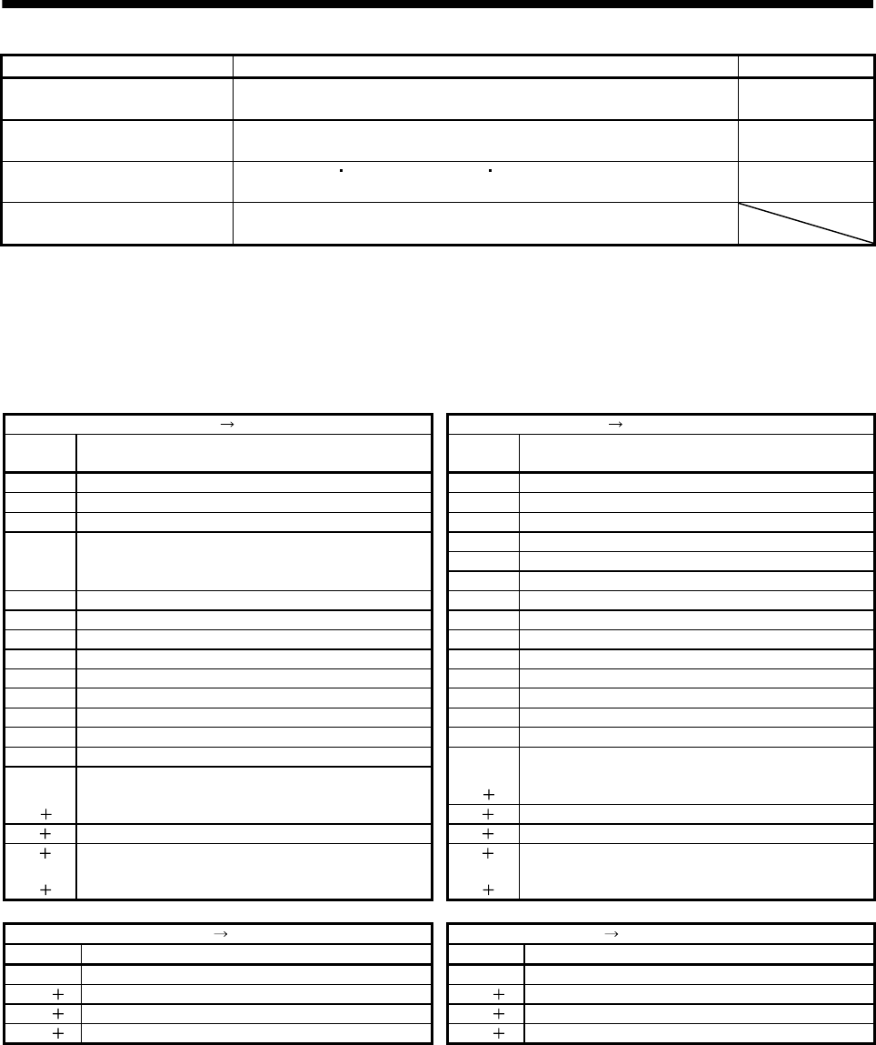
Programmable controller Servo amplifier (RWwn) Servo amplifier Programmable controller (RWrn)
Address No. Signal Address No. Signal
RWwn Monitor 1 RWrn Monitor 1 data
RWwn 1 Monitor 2 RWrn 1 Monitor 2 data
RWwn 2 Instruction code RWrn 2 Respond code
RWwn 3 Writing data RWrn 3 Reading data
Note. "n" depends on the station number setting.